Effects of Electromagnetic Shielding in Electron Microscopy Lab Environment (Part 6 ) Temperature, Humidity, Airflow and Noise
Temperature
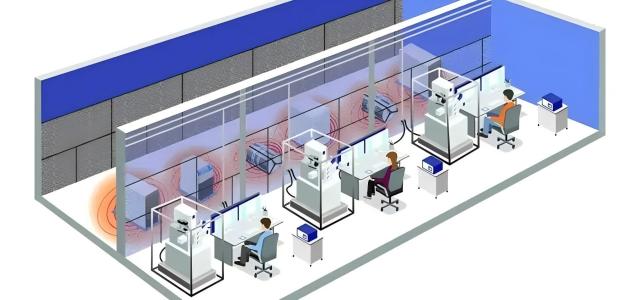
The temperature requirements for Electron Microscopes are not particularly high. Typically, temperatures around 26 degrees Celsius in summer and 20 degrees Celsius in winter are acceptable for comfort and energy efficiency. However, the temperature change rate is important, with common requirements being ≤0.5°C/3 minutes or ≤0.5°C/5 minutes.
Good-quality central air conditioning systems can usually meet these requirements. For example, a well-known brand of split air conditioner has a four-minute cycle with temperature fluctuations of around 1 degree Celsius. Using precision air conditioning systems usually doesn't offer significant benefits in terms of price, maintenance costs, and applicability.
In practice, High-precision Electron Microscopes tend to be bulky and have larger heat capacities. As long as the temperature variation inside the room is not significant, minor fluctuations within a short period are unlikely to have a noticeable impact.
It's important to avoid excessively low temperatures in the electron microscope room to prevent condensation and dripping water on cooling water pipes, liquid nitrogen pipes, and Dewar flasks. For example, there was a case where an improperly placed old-fashioned spectroscopic circuit board under a liquid nitrogen Dewar flask got damaged due to condensation dripping.
Regarding auxiliary equipment rooms, such as those housing circulation cooling water tanks, air compressors, uninterrupted power supply (UPS) units, and vacuum pumps, it's necessary to calculate the required capacity of the air conditioning system based on the heat dissipation provided in the equipment specifications.
If the temperature in the auxiliary equipment room is too high, it can reduce the cooling efficiency of the circulation cooling water tank and increase the thermal drift of lenses.
Therefore, it is recommended to keep the temperature in the auxiliary equipment room below 35 degrees Celsius throughout the year.
Humidity
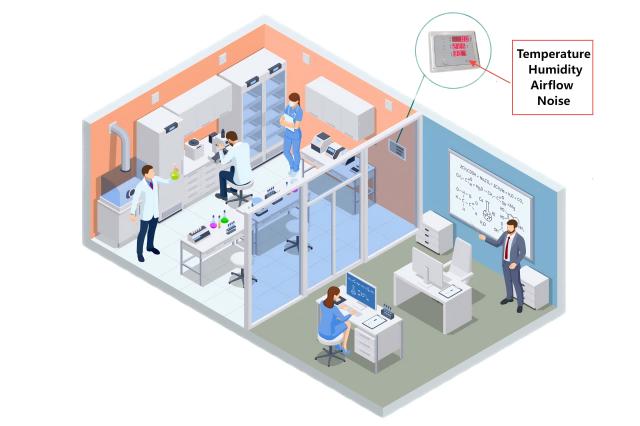
Frozen samples have high humidity requirements, and some users prefer a relative humidity below 25%. However, extremely low humidity can lead to electrostatic discharge. To address this, the freeze-fracture preparation machine can be moved closer to the Electron Microscope to minimize the exposure time of frozen samples, thereby reducing the humidity requirements.
Usually, relative humidity of below 65% is sufficient for the electron microscope room, which is a relatively low requirement that most air conditioning systems can easily meet (assuming the room door is kept closed and the time for personnel entry and exit is minimized).
If it is a newly constructed building within a year, it may take some time to eliminate the building's moisture. In such cases, a dehumidifier can be added to regulate the humidity.
Airflow
Another consideration is the airflow from the air conditioning system. In most cases, as long as the air conditioning outlets (whether mounted or cabinet-type) are not directly facing the microscope column during the layout planning of the electron microscope room, the issue of airflow is generally not a major concern. For high-demand Electron Microscopes, using cloth bags for air supply can be considered.
As indicated by the formula airflow = air velocity × air outlet area, increasing the outlet area can reduce the air velocity while maintaining the same airflow.
A successful case from a university involves an approximately 50 square meter Electron Microscope room with a nearly square floor plan. Two air supply outlets (1m x 1m cross-section) were placed diagonally on the roof, and two return air outlets (0.8m x 0.8m cross-section) were placed on opposite diagonal corners. This arrangement allowed the airflows to flow along the walls, effectively achieving the air supply task, and creating a "quiet zone" near the microscope column (which is located near the center of the room). Multiple tests showed that the air velocity reached 0.00 m/s.
Noise
Noise is another issue to consider, as even the volume of a phone call can cause horizontal interference stripes (similar to jagged lines caused by magnetic interference) in images with magnifications over 100,000 times.
If it is not possible to move the noise source away, the walls and ceiling can be covered with flame-retardant foam materials for sound absorption. Micro-perforated panels (made of iron or aluminum composite panels, for example) should be used for the walls. Foam materials with a thickness of 40-80mm generally provide noticeable sound absorption effects.
In general, as long as the door is closed and no one speaks, the impact of noise interference can be negligible.
Conclusion
This series of electron microscope installation environment pictures, texts, and recommendations are based on practical experience gained from over a decade of site surveys and renovations. It holds a high reference value.
The site conditions are of significant importance to the performance of electron microscopes.
Therefore, it is highly recommended to let professionals handle their respective areas of expertise. Both users and manufacturers should engage professional companies and personnel for site surveys and renovations. In addition, a rigorous supervision mechanism and clear accountability system should be established to prevent the participation of unscrupulous practitioners and the loss of equipment efficiency.
Furthermore, the studio strongly urges electron microscope users and relevant personnel from manufacturers to actively participate and enhance their understanding of electron microscope installation environments. This will ensure that valuable national and corporate funds are utilized to their fullest.
