Effects of Electromagnetic Shielding in Electron Microscopy Lab Environment (Part 5) The Grounding of Electron Microscopes
As is well known, electrical equipment requires grounding for safety protection. The outer casing or exposed metal parts of various devices need to be directly connected to the earth to ensure that in the event of a short circuit or leakage, the voltage on the casing or exposed metal parts remains within a safe range for human contact (the current safety standard specifies a voltage not exceeding 24V), thus ensuring personal safety.
Electron Microscopes are no exception and also require grounding for safety. In the event of a system leakage, a discharge path is provided to ensure the safety of operators or maintenance personnel.
However, there is a special requirement for Electron Microscopes. The grounding wire of the electron microscope serves as the common "zero potential" reference point for various subsystems within the electron microscope (such as detectors, signal processing amplifiers, electron beam control, etc.), and the voltage must be stable at zero potential.
In theory, the grounding wire is a reference point with zero voltage. However, in practice, when there is a current in the grounding circuit (this current is usually referred to as leakage current or ground current, which is the vector sum of the leakage currents generated by various electrical equipment), any grounding terminal in the grounding circuit will have a ground voltage (because the grounding resistance of any grounding wire, although small, cannot be zero, according to Ohm's law V=IR, the ground voltage V will not be zero when the leakage current I is non-zero).
Although this ground voltage is usually negligible, for Electron Microscopes that often need to magnify images by tens of thousands to millions of times, the resulting impact is often significant and cannot be ignored.
The fluctuation of the ground voltage directly causes artifacts similar to magnetic fields and vibration interference at the vertical edges of the scanned image, and in severe cases, it can cause image shaking.
The solution to this problem is simple, which is to set up a dedicated grounding circuit specifically for the electron microscope, which is referred to as a "single earth loop." This eliminates the interference from the leakage currents of other electrical devices on the same power circuit to the Electron Microscope.
Note that the grounding body, grounding wire, and grounding terminal must all be independent and not connected to any conducting body to ensure the complete independence of the grounding wire.
The following common errors should be avoided:
1) Not installing a completely independent grounding body, but simply laying a grounding wire connected to a common grounding body.
2) Although there is a separate grounding body, the grounding wire or grounding terminal is connected to a common ground wire or other electrical devices.
3) Try to avoid using "equipotential terminal boxes" that are usually connected to the common ground wire or are shorted to light steel keels.
4) Try to avoid using a single grounding wire for two or more electron microscopes (some users have multiple microscopes and are reluctant to install a separate grounding wire for each microscope).
5) Do not use existing underground metal conductors as the grounding body, such as reinforcing bars in the bottom beams of buildings, as they are public property. Do not borrow the grounding body of the weak current system, as they are not reliable.
The grounding resistance requirement for electron microscopes is not high in practice. A few years ago, a certain brand required a resistance of below 100 ohms. Currently, most manufacturers require a resistance of 1 to 10 ohms.
Grounding construction generally includes "deep well type" and "shallow pit type" methods (see Figures 1 and 2). Note that regardless of the method used, a distance of more than four meters should be maintained in a straight line from the grounding body to any underground metal to prevent interference.
Deep well-type construction instructions (for reference):
1. Drill a deep hole: with a diameter of about 50-100 millimeters and a depth of about 3-20 meters, reaching a damp soil layer is sufficient.
2. Grounding body: a copper pipe with a wall thickness of 2 millimeters (a copper rod can also be used) with a diameter of about 30 millimeters and a length of about 0.5 meters, welded to the grounding wire (at least three points) and led to the vicinity of the electron microscope.
3. Grounding wire: 4-10 square millimeters of rubber or plastic multi-strand copper core wire.
4. Conductivity improver: about 2-3 kilograms of salt and charcoal.
5. Construction process: Place the grounding body at the bottom of the hole, prepare a long and thin tool (rebar, water pipe, etc.), gradually fill the conductivity improver from the bottom up and compact it, then continue backfilling and compacting, paying special attention to compacting and tightening around the grounding body, and be careful not to break the grounding wire.
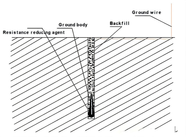
Figure 1. Deep well type diagram
Shallow pit type construction instructions (for reference):
1. Excavate a shallow pit with a depth of about 0.5-2 meters, reaching a damp soil layer is sufficient.
2. Grounding body: a copper plate of about 0.5×0.5 meters with a thickness of 2-3 millimeters, welded to the grounding wire (at least three points) and led to the vicinity of the electron microscope.
3. Grounding wire: 4-10 square millimeters of rubber or plastic multi-strand copper core wire.
4. Conductivity improver: about 2.5-5 kilograms of salt and charcoal.
5. Construction process: Place the copper plate vertically at the bottom of the pit, first cover it with the conductivity improver, compact and tighten it, then continue backfilling and compacting, being careful not to break the grounding wire.
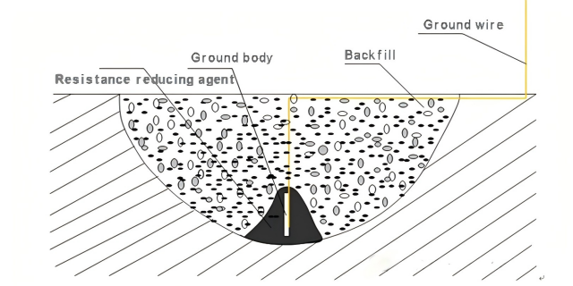
Figure 2. Shallow pit diagram
The "deep well type" is suitable for places where it is difficult to excavate the ground or the groundwater level is deep. Generally speaking, the "shallow pit type" is the more common method.
Regardless of the "deep well type" or "shallow pit type," according to this construction process, the grounding resistance can be achieved between 4 and 10 ohms (for a single grounding body).
In places where the soil resistance is high, multiple grounding bodies can be connected to form a small grounding system to reduce the grounding impedance. In this case, the distance between each grounding body should be 0.3-0.5 meters (the same borehole can be used for the deep well type).
Through actual testing, the grounding resistance of a single grounding body is typically around 4 ohms, two grounding bodies are around 3 ohms, three grounding bodies are around 2 ohms, and six to ten grounding bodies can achieve a resistance of below 1 ohm (depending on the soil resistivity).
Since the danger of "step voltage" does not exist, there is no need to follow the practice of a lightning protection grid grounding system.
At the same time, to reduce the influence of other underground conductors nearby, this small grounding system should occupy as little underground area as possible.
To prevent accidental short circuits, the grounding wire should be directly connected to the grounding wire of the Electron Microscope (or the grounding bus inside the electron microscope), without using common grounding boxes or terminal boxes, not entering other equipotential terminal boxes or switch boxes, and not being connected to busbars.