Air conditioners have become an essential part of our everyday lives, keeping us cool and comfortable even during the hottest months of the year. Over the years, these appliances have undergone significant advancements, thanks to the introduction of electronic control boards and Printed Circuit Board Assemblies (PCBAs). In this blog post, we will explore the evolution and importance of air conditioner electronic control boards, universal control boards, PCBA for electronic products, and the manufacture of air conditioner PCBAs, including those for automotive applications.

1. What are Air Conditioner Electronic Control Boards?

Air conditioner electronic control boards, also known as PCBAs, are crucial components that control the various functions of an air conditioning system. They are responsible for regulating temperature, fan speed, mode settings, and other operations required for efficient cooling. These control boards are designed to ensure precise and accurate control, offering users enhanced comfort and energy efficiency.

2. The Role of Universal Control Boards

Universal control boards are a revolutionary development in air conditioning technology. Unlike traditional control boards, which are specifically designed for certain models or brands, universal control boards provide a streamlined solution for various air conditioner types. They offer compatibility with multiple brands and models, reducing the need for different control boards and simplifying maintenance and repairs.

3. PCBA for Electronic Products

The usage of PCBA extends beyond air conditioners. PCBA for electronic products refers to the manufacturing of Printed Circuit Board Assemblies used in a wide range of electronic devices. Whether it’s a smartphone, television, or home automation system, PCBA plays a vital role in ensuring the functionality and reliability of these products. The advancements in PCBA technology have led to smaller, more efficient, and cost-effective electronic devices.

4. Manufacturing Air Conditioner PCBAs

The manufacture of air conditioner PCBAs requires precision and expertise. Specialized manufacturing processes and quality control measures ensure the reliability and longevity of these components. From the selection of high-quality materials to the assembly of intricate electronic circuits, every step is critical to achieving optimal performance. Additionally, automated production techniques have improved efficiency, resulting in faster turnaround times and reduced costs.

5. Automotive PCBA for Air Conditioners

Automotive PCBA for air conditioners is a specialized application of PCBA technology. With the increasing number of electronic components and advanced features in modern vehicles, including climate control systems, efficient PCBAs are crucial. These automotive PCBAs not only control the air conditioning system but also integrate with other vehicle systems, providing a seamless experience for drivers and passengers.

In conclusion, the introduction of air conditioner electronic control boards, universal control boards, PCBA for electronic products, and specialized automotive PCBAs has transformed the air conditioning industry. The integration of advanced technologies and manufacturing processes has led to more efficient, reliable, and cost-effective solutions. Whether it’s ensuring optimal climate control in homes or enhancing comfort during road trips, these advancements have made air conditioning systems an indispensable part of our lives.

Are you experiencing issues with your refrigerator’s performance or control? Look no further! In this comprehensive guide, we will delve into the world of refrigerator PCB assembly, specifically focusing on electronic refrigerator PCB boards and timer control boards. Whether you’re a factory manager or a homeowner, understanding the intricacies of these important components is crucial for efficient refrigerator operation.

What is a Refrigerator PCB Assembly?

A refrigerator PCB assembly, also known as a printed circuit board assembly, is a vital component of modern refrigerators. It acts as the central nervous system, controlling various functions and ensuring the smooth operation of your refrigerator. From managing the temperature to controlling the compressor and defrosting cycles, the PCB assembly plays a critical role in maintaining the freshness of your food.

Electronic Refrigerator PCB Boards Explained

Electronic refrigerator PCB boards encompass a range of interconnected electronic components that work together to regulate the refrigerator’s operation. These boards are responsible for translating commands from the user interface and sensors into actions performed by the refrigerator’s components. In essence, they act as the brain, directing the refrigerator on when to cool, defrost, and maintain optimal temperature levels.

Manufacturers design electronic refrigerator PCB boards to be efficient, reliable, and durable, using high-quality materials and advanced manufacturing processes. This ensures that your refrigerator remains at peak performance for an extended period, minimizing the chance of costly repairs or replacements.

The Importance of Factory Electronic Refrigerator PCB Boards

When it comes to factory electronic refrigerator PCB boards, the stakes are even higher. These boards are specifically manufactured for industrial-grade refrigerators used in food production, storage, and distribution facilities. They need to withstand harsher conditions, ensure precise temperature control, and offer enhanced durability to meet the demanding needs of commercial operations.

Factory electronic refrigerator PCB boards go through rigorous quality control and testing processes, adhering to strict industry standards and regulations. This guarantees their reliability and stability in challenging environments, where continuous operation is essential.

Timer Control Board and Efficient Refrigeration

The timer control board is a vital part of refrigerator PCB assemblies, particularly in systems with automatic defrost functionality. This component regulates the defrost cycles in the refrigerator by activating the defrost heater and terminating the defrost process at the appropriate time. By ensuring proper defrosting intervals, the timer control board prevents frost buildup, optimizing the refrigerator’s energy efficiency and prolonging its lifespan.

Conclusion

Understanding refrigerator PCB assemblies, electronic refrigerator PCB boards, factory electronic refrigerator PCB boards, and the role of timer control boards is crucial for anyone involved in the refrigerator industry. Whether you’re a homeowner looking to troubleshoot issues or a factory manager seeking optimal performance in your industrial refrigeration units, having knowledge about these components empowers you to make informed decisions and take necessary steps to maintain the efficiency and longevity of your refrigerators.

So, next time you encounter any refrigerator-related concerns, remember that the PCB assembly and its various components, such as the electronic PCB board and timer control board, play pivotal roles in ensuring your refrigerator functions smoothly and efficiently.

Products or services related to refrigerator parts play a crucial role in maintaining the efficiency and functionality of both home and car refrigerators. Two commonly discussed components in this realm are refrigerator PCB assembly and refrigerator PCB board. In this article, we will compare and contrast these two options, shedding light on their features, benefits, and applications.

Refrigerator PCB Assembly

A refrigerator PCB assembly, also known as a Printed Circuit Board assembly, is a complex electronic module that controls and coordinates various functions of a refrigerator. It acts as the brain of the appliance, facilitating the communication between different components and ensuring optimal performance. Common features of refrigerator PCB assemblies include:

  1. Durability and Reliability: PCB assemblies are designed to withstand harsh environmental conditions, ensuring longevity and reliability for the refrigerator.

  2. Enhanced Functionality: With advanced technology integrated into the PCB assembly, it allows for precise temperature control, defrosting cycles, and overall energy efficiency.

  3. Diagnostic Capabilities: Some PCB assemblies come with built-in diagnostic tools that detect malfunctions and assist in troubleshooting, making repairs quicker and easier.

Refrigerator PCB Board

A refrigerator PCB board, also referred to as a Printed Circuit Board or control board, is a smaller component that serves as the control interface for the refrigerator. It manages specific functions and electrical connections within the appliance. Key features of refrigerator PCB boards include:

  1. Compact Design: PCB boards are smaller compared to the PCB assembly, making them more suitable for compact refrigerators or specific control functions.

  2. Cost-Effective: As a standalone unit, PCB boards can be a more budget-friendly option for replacing a faulty control system in a refrigerator.

  3. Easy Replacement: Since PCB boards are designed as modular components, they can be easily replaced in case of malfunction without requiring extensive technical knowledge or expertise.

Choosing the Right Option for You

When it comes to selecting the right refrigerator part, there are a few factors to consider. If you have a larger refrigerator or require advanced functionalities such as diagnostic capabilities, a refrigerator PCB assembly might be the ideal choice. On the other hand, if you have a compact refrigerator or need a cost-effective solution with easy replacement, a refrigerator PCB board can offer the desired benefits.

It’s essential to consult the specific refrigerator model’s documentation or seek the advice of a professional technician to ensure compatibility and suitability for your needs. Remember, each appliance has unique requirements, and utilizing the appropriate refrigerator part can make a significant difference in the overall performance and longevity of your refrigerator.

In conclusion, whether you opt for a refrigerator PCB assembly or a refrigerator PCB board, both options have their merits. Understanding your specific needs and the capabilities of each component will help you make an informed decision. Consider factors like functionality, size, and cost before making a purchase. By doing so, you can ensure that your refrigerator continues to keep your food fresh and cool efficiently.

Year 2024, global attention once again turns to China, as this year marks the beginning of an important zodiac cycle—the Year of the Dragon. The dragon, a mythical creature in Chinese traditional culture, carries rich symbolism and significance. For us consumers living in foreign lands, understanding the cultural significance of the Year of the Dragon may offer some interesting connections to our daily technological lives.

Traditional Symbolism of the Year of the Dragon

In Chinese culture, the dragon is seen as a symbol of power, wisdom, and prosperity. The Year of the Dragon is often considered a year full of hope and opportunities. During this year, people hope to embody the dragon's strong vitality and boundless creativity.

Integration of Technology with the Year of the Dragon

When we talk about technology, electronic devices such as computers, tablets, and smartphones have become indispensable parts of our lives. So, how can we connect the symbolism of the Year of the Dragon with these modern technological products?

Imagine our electronic devices as parts of the dragon's body. The computer is like the dragon's brain, responsible for handling complex tasks and information; the tablet is like the dragon's wings, allowing us to work and entertain ourselves anytime, anywhere; and the smartphone is like the dragon's eyes, enabling us to stay connected with the world at all times.

And the USB charger is the "heart" that provides energy to these electronic devices. Just as the dragon needs food and water to stay vibrant, our electronic devices need charging to stay in optimal condition. In the Year of the Dragon, choosing a high-quality 5 Ports USB charger is like infusing new vitality into our devices, enabling them to serve us better.

Conclusion

The Year of the Dragon in 2024 is not just a traditional zodiac cycle but also a moment of integration between tradition and modernity, culture and technology. Let us not only feel the traditional symbolism of the Year of the Dragon in this special year but also combine these symbols with our modern technological lives, adding more color and vitality to our lives.

RF-star unveils automotive-grade Bluetooth Low Energy module RF-BM-2642QB1I based on TI CC2642R-Q1 ACE-Q100 compliant MCU. The BLE module brings enhanced security, reliability and a friendly user experience for automotive applications, including Passive Entry Passive Start (PEPS), Phone as a Key (PaaK), and Battery Management Systems (BMS).


Automotive Grade BLE Module RF-BM-2642QB1I Empowering Connected Vehicles

Automotive Grade BLE Module RF-BM-2642QB1I Empowering Connected Vehicles


To meet the stringent demands of automotive environments, the RF-BM-2642QB1I module features a 48-MHz Arm® Cortex®-M4F processor with 352 KB Flash and 88 KB RAM, providing ample storage capacity for various automotive functionalities. With a wide operating temperature range from -40℃ to 105℃and compliance with AEC-Q100 automotive specifications, the CC2642R-Q1 module ensures robust performance even in challenging conditions. Here are the key highlights include but are not limited to:

Key Features of the CC2642R-Q1 Module

  • Low Power Consumption: With a low standby current of 2.49uA and 25.58uA TX at 0 dBm, RF-BM-2642QB1I extends its battery life, making it ideal for power-sensitive automotive applications.
  • Excellent RF Performance: Excellent radio sensitivity and robustness (selectivity and blocking) performance for Bluetooth ® Low Energy (-105 dBm for 125-kbps LE Coded PHY, -97 dBm for 1-Mbps PHY). Its TX power reaches up to + 5 dBm with temperature compensation.
  • Compliant with AEC-Q100: Certified for Grade 2 temperature range (–40 °C to +105 °C), the CC2642R-Q1 module provides pre-installed vehicle applications with reliable stability and durability.
  • Rich Peripherals: In addition to supporting Bluetooth® 5.2 features and earlier Low Energy specifications, the new automotive-grade module offers a variety of digital peripherals. They can route to any of 31 GPIOs, including UART, I2S, I2C, SPI, and ADC, enhancing versatility in automotive designs.

Moreover, RF-star automotive module RF-BM-2642QB1I supports Bluetooth Low Energy 5.0 serial port transmission, facilitating seamless integration with UART function for 4 working modes. It operates in master-slave mode, slave mode, master mode and beacon mode. When a device is in a master mode or master-slave mode, it supports connecting up to 7 slave devices at the same time. Its rich functions with AT commands can reduce design complexity in your development and help products quickly flow to the market.


Furthermore, the module enables over-the-air(OTA) updates for firmware deployment, streamlining the upgrade process for OEMs and end-users.


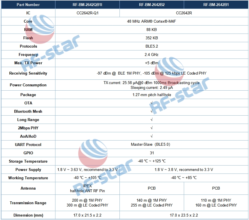
The CC2642R-Q1 module is pin-to-pin compatible with RF-star’s CC2642R series modules RF-BM-2642B1 and RF-BM-2642B2, ensuring easy integration and scalability for automotive applications. Here is a model list of CC2642R series Bluetooth LE modules to clearly show their differences.

Model list of RF-star CC2642R series modules

Model list of RF-star CC2642R series modules

Its versatility extends across a wide range of use cases, including:

Car Access

Combined with the Received Signal Strength Indicator (RSSI) algorithm and CC2642R-Q1 Bluetooth nodes, the localization between the mobile phone and the vehicle can be measured accurately. So, it is well-suited for PEPS, RKE, and PaaK systems.

Battery Management Systems (BMS)

With its low power consumption and AEC-Q100 qualification, the module enhances the security, flexibility, and efficiency of BMS solutions in automotive applications.


Besides, RF-star automotive-grade module also applies to advanced driver assistance systems (ADAS), and telematics control units (TCU).


Beyond automotive use, the RF-BM-2642QB1I module finds applicability in industrial transportation, asset tracking, factory automation, and control systems, thanks to its capabilities for advertising extension, Bluetooth mesh, direction finding and long-range transmission.

Driving Innovation in IoV and IoT

In alignment with the burgeoning smart vehicle landscape, RF-star remains committed to advancing the Internet of Vehicles (IoV) industry. Over the past year, RF-star has successively become member of the Car Connectivity Consortium (CCC), and the Intelligent Car Connectivity Industry Ecosystem Alliance (ICCE), and was fortunate to draft UWB System Requirements.


“Now, its cost-effective Bluetooth Low Energy modules have been widely adopted in automotive applications, such as the BLE PEPS." Ben Qiu, GM of RF-star. "Our new wireless modules and solutions combination with UWB and BLE technologies will provide more accurate location and reliable connectivity for automotive, industrial, and other applications, further driving the innovation of IoV and IoT."


For more information about automotive-grade modules, please visit www.rfstariot.com or reach out to us at info@szrfstar.com.

Introduction:
In today's rapidly evolving telecommunications industry, accurate testing and measurement of optical networks are critical for ensuring reliable performance. The Red Light Optical Power Meter (OLP) is a cutting-edge testing instrument that combines the functionalities of an Optical Time Domain Reflectometer (OTDR) and an Optical Power Meter (OPM). This article aims to provide an overview of the Red Light OLP, highlighting its features, benefits, and applications in the field of optical network testing.

Features and Functionality:
The Red Light OLP integrates the capabilities of both an OTDR and an OPM in a single device, making it a versatile and convenient solution for network technicians. It utilizes red light technology, which allows for accurate power measurement and characterization of fiber optic networks. The device features a high-resolution touchscreen interface, intuitive software, and a compact design for ease of use and portability.

OTDR Function:
The Red Light OLP's OTDR function enables technicians to analyze the optical loss and reflectivity of fiber optic cables. It can precisely locate fiber breaks, splice points, and other anomalies in the network. With its advanced pulse width options and dynamic range, it provides accurate distance and attenuation measurements, enabling technicians to troubleshoot network issues effectively.

OPM Function:
In addition to OTDR capabilities, the Red Light OLP serves as a highly accurate OPM. It can measure optical power levels with high precision and is compatible with various wavelengths commonly used in fiber optic networks. This feature allows technicians to verify signal power levels, identify power discrepancies, and monitor network performance efficiently.

Benefits and Applications:

The Red Light OLP offers several benefits that make it an indispensable tool for network testing. Its compact size and comprehensive functionality eliminate the need to carry multiple devices, reducing equipment costs and simplifying on-site operations. The device's high measurement accuracy and digital signal processing capabilities improve testing efficiency, leading to faster troubleshooting and reduced downtime.


The Red Light OLP finds extensive applications in numerous areas of optical network testing. It is widely used in the installation and maintenance of telecommunication networks, including fiber-to-the-home (FTTH), data centers, and Ethernet networks. Additionally, it proves invaluable in troubleshooting network issues, identifying faulty components, and optimizing network performance.


Conclusion:
The Red Light Optical Power Meter combines the best features of an OTDR and an OPM, providing technicians with a powerful testing solution for optical networks. With its ability to accurately measure optical power levels and identify network anomalies, the Red Light OLP is an essential instrument for ensuring the efficient operation and maintenance of fiber optic networks. Its compact design, extensive functionality, and ease of use make it a preferred choice for network technicians in the telecommunications industry.

With the increasing demand for efficient cooling solutions in today’s fast-paced digital world, it’s crucial to have a reliable and versatile fan controller to keep your PC running optimally. At [Company Name], we take pride in offering cutting-edge fan PCBA controller and design services that cater to every customer’s unique needs.

Our fan PCBA controller is designed to provide precise control over your fan’s speed, ensuring optimal cooling performance while keeping noise levels at a minimum. With advanced features such as temperature sensing, automatic heat and cool electric fan assembly, and customizable settings, our digital fan controller takes your PC cooling to a whole new level.

One of our latest innovations is the state-of-the-art fan controller board designed specifically for table mode. This compact yet powerful PCB controller offers a seamless user experience, allowing you to effortlessly adjust fan speeds and monitor temperature levels directly from your desktop. Its sleek design and intuitive interface make it the perfect addition to any PC setup.

What sets our fan controller board apart is its unparalleled versatility. Our team of experts has carefully engineered it to be compatible with a wide range of fans, ensuring compatibility with different PC configurations. Whether you’re an avid gamer, a video editor, or a content creator, our fan controller board delivers exceptional cooling performance while enhancing the overall aesthetics of your PC.

Our commitment to excellence doesn’t stop at providing top-notch products. We also offer fan PCBA design services, tailored to suit businesses and individuals seeking customized cooling solutions. Our experienced engineers collaborate closely with clients to understand their requirements and design a fan controller PCB that perfectly aligns with their specifications.

At [Company Name], we understand the importance of efficient and reliable cooling systems to safeguard your PC’s performance. That’s why we strive to deliver exceptional products and services, continuously pushing the boundaries of innovation in the cooling industry.

Invest in our cutting-edge fan PCBA controller and design services today, and experience a whole new level of precision, performance, and peace of mind. Stay cool even during the most intense tasks with our revolutionary fan controller board that exceeds expectations.

Contact us now to explore the possibilities and transform your PC cooling experience. Together, let’s take your cooling game to the next level!

Are you tired of manually adjusting the speed of your cooling fans? Do you want a more efficient way to control the temperature in your space? Look no further! With the new style remote control available cooling fan circuit boards, you can effortlessly regulate the airflow and create the perfect environment for your needs. In this guide, we will take you through a step-by-step process on how to use these innovative circuit boards. Whether you’re a beginner or have some prior knowledge, this guide will provide you with the necessary information to get started.

Step 1: Familiarize Yourself with the Cooling Fan Circuit Board

Before diving into the specifics, it’s essential to understand the basic components of the cooling fan circuit board. Take a moment to familiarize yourself with the board’s various sections, including the power supply, input/output ports, and control buttons. Reading the instruction manual that accompanies the circuit board can provide valuable insights as well.

Step 2: Install the Circuit Board

To use the cooling fan circuit board, you must first install it in the appropriate location. Identify a suitable mounting position within the cooling system and secure the board using the provided screws or adhesive. Ensure that the installation is firm and stable to prevent any damage or dislodging during operation.

Step 3: Connect the Cooling Fans

Connect the cooling fans to the designated ports on the circuit board. Most boards have multiple ports to accommodate several fans simultaneously. Make sure to match the correct fan wire with the appropriate port to ensure proper functionality. Secure the connections to avoid any loose wiring.

Step 4: Power Up the Circuit Board

Once the fans are connected, it’s time to power up the circuit board. Connect the power supply to the designated port on the board and plug it into a reliable power source. Ensure that the power supply matches the board’s specifications to prevent any electrical issues or damage. Once connected, switch on the power supply to activate the circuit board.

Step 5: Test and Adjust Fan Speed

Now that the circuit board and fans are powered up, it’s time to test their functionality. Use the remote control provided with the board to adjust the fan speed. Most remote controls have intuitive buttons for increasing or decreasing the speed. Experiment with different settings to find the optimal airflow for your needs. You can also test the remote control’s range by adjusting the speed from different positions within the room.

Step 6: Additional Features and Considerations

New style remote control available cooling fan circuit boards often come with additional features to enhance your experience. Familiarize yourself with these features, such as temperature sensors, timer settings, and auto mode. Experiment with these options to customize the cooling system based on your preferences and requirements.

Conclusion

Using new style remote control available cooling fan circuit boards has never been easier. By following these simple steps, you can effortlessly control the airflow and temperature in your space, providing comfort and convenience. Whether you’re a beginner or have some experience with circuit boards, these user-friendly devices will undoubtedly revolutionize your cooling system. Enjoy the benefits of a more efficient and personalized cooling experience with the new style remote control available cooling fan circuit boards.

What Is Membrane Switch Keypad?


A membrane switch keypad is a type of keypad or keyboard that utilizes a membrane switch as its primary input mechanism. It is a thin and flexible keyboard design that consists of several layers of materials, including the top membrane layer, circuit layer, spacer layer and bottom adhesive layer.

The top membrane layer is called as graphic overlay,typically made of a thin, flexible, and transparent material such as polyester or polycarbonate. It is printed with symbols(which indicate the functions of the buttons or keys), icons, or labels that represent the keys or buttons on the keypad. These labels are usually printed on the underside of the top membrane layer to protect them from wear and tear.

Beneath the overlay is the printed circuit layer, which is made of conductive material such as copper or silver ink. It contains the circuitry and pathways that connect the keys or buttons to the electronic device.

The circuit layer is sandwich ed between the two membrane layers and contains the conduct ive traces or circuits that form the switch contacts. When a key or button on the keypad is pressed, the top membrane layer flex es and makes contact with the circuit layer, completing the electrical circuit and registering the input.

A spacer layer, often made of polyester or polyethylene, separates the graphic overlay from the printed circuit layer. It provides a cushioning effect and helps maintain the proper spacing and alignment of the keys.

The bottom layer of the membrane switch keypad is an adhesive layer that allows the keypad to be securely attached to the electronic device or housing. The bottom layer acts as a backing for the circuit layer and provides structural support. It is also made of a thin and flexible material.

Mebrane switch keypads offer several advantages over traditional mechanical keypads. Membrane switch keypads are popular in various industries and applications due to their flexibility, durability, and cost-effectiveness. They are also more resistant to dust, moisture, and other environmental factors, making them suitable for various applications. Additionally, membrane switch key p ads can be customized with different colors, shapes,icons, backlighting,waterproof and other features to meet specific user requirements.

Overall, membrane switch keypads provide a reliable, cost-effective, and versatile input solution for a wide range of electronic devices, including appliances, industrial equipment, medical devices, and consumer electronics.

As long as you want, no we can't do. Please don't hesitate to contact us, tell us your need,One Stop Soluction INO Technology will give you the most satisfactory reply. 


INO Technology is leading membrane keypads, keyboards and switches manufacturer, supplier and exporter in China since last 10 years. We are well-known across every sector for designing and manufacturing customized membrane keypads like flexible and PCB-based membrane keypads. We have experienced designing team, which understands customers' requirements and selects components and designs accordingly.

We are unique in terms of manufacturing keypads as we are equipped with in-house advanced machinery and climatically controlled 10.000 clean rooms. We are ISO 9001:2015 Quality management certified organization, which prompts us to be an internationally acclaimed organization for membrane keypads and keyboards.A membrane switch or touch switch is a multi-layered user interface device that acts as a switch to turn a device on or off. Membrane switches are printed circuits on film as opposed to mechanical switches, which are often made of copper and polymers. Silver or carbon ink is printed onto heat-stabilized polyester film to create membrane switches. As the switch’s graphic interface, an overlay is placed on the initial surface. These top substrates are known as “membranes” or “graphic overlay films” since they are constructed of thin, pliable materials.


Membrane switches may be categorized as user-equipment interface utilities, which are simply utilities that allow users to successfully communicate commands to electronic devices. They should not be confused with mechanical switches, which are composed of plastic parts and copper instead of a circuit and a substrate.

Membrane switches have a low profile, sealing ability, and ease of cleaning. Membrane switches can be used in conjunction with other control systems such as keyboards, touch screens, and lighting, and they can be as complex as membrane keyboards and switch panels found in mobile phones and computers. Membrane switches are also known as membrane keyboards and membrane keypads, depending on the industry and application.