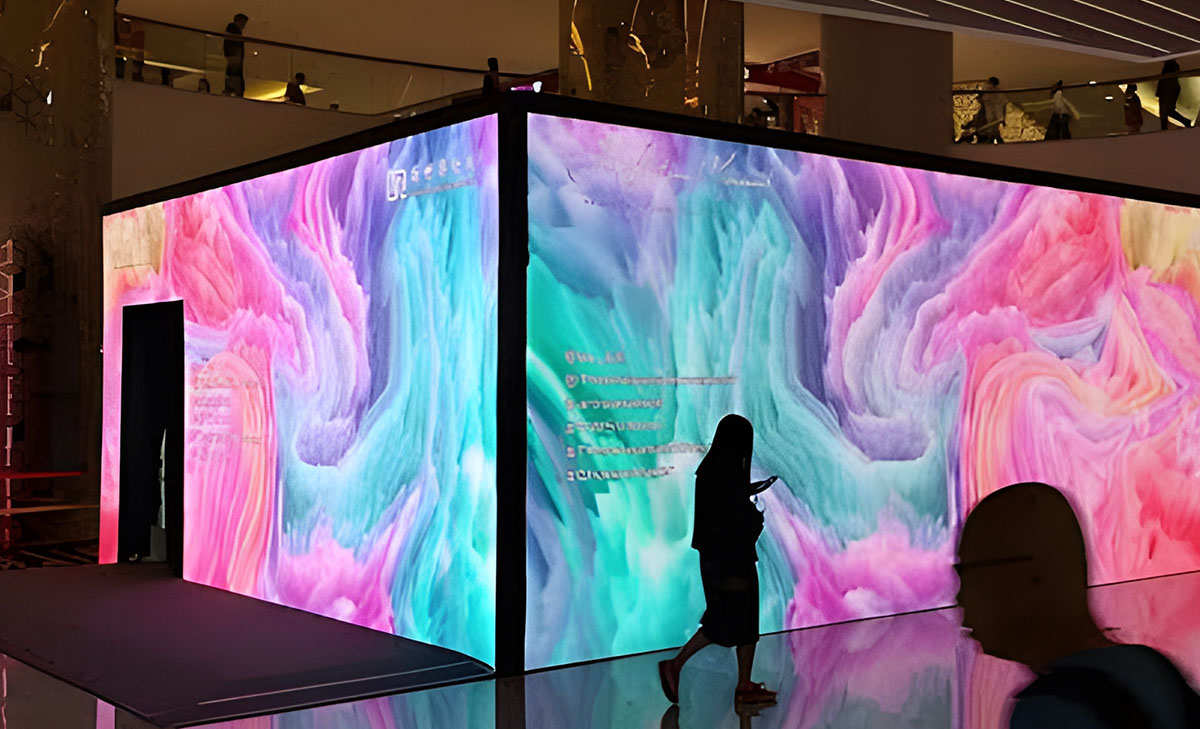
In modern cities, advertisements are omnipresent, especially in high-traffic areas such as highways, shopping malls, and public squares. However, as advertising screen technology has advanced, a common challenge has persistently plagued the industry: glare. Today, we explore how glassless LED display screens completely solve this problem, providing viewers with a clearer and more enjoyable visual experience.


LED Digital Billboards


For advertisers, glare not only diminishes the effectiveness of their ads but also risks losing potential customers who might miss critical information. The advertising industry has long sought solutions to the glare problem, and glassless LED display screens are the ultimate solution to this issue.


Glassless Design: A Revolutionary Technological Breakthrough

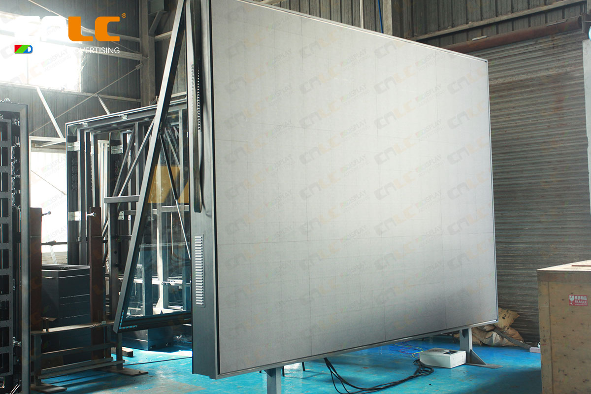
CNLC's LED Digital Billboard screens feature a glassless design, eliminating the common problem of light reflections on traditional screens. Without the reflective surface of glass, these screens can deliver clear visual effects under various lighting conditions, allowing viewers to easily grasp the advertising message.


LED Digital Billboard screens


Why is the glassless design so important?


Significantly Improved Clarity: Without glass, the LED Billboard display screen surface is free from glare, ensuring clear content visibility whether under bright sunlight or nighttime neon lights.


Reduced Light Pollution: The glassless design not only reduces visual interference but also effectively lowers light pollution, which is particularly crucial in city centers and areas with strict light control regulations.


Additional Advantages of Glassless Design: Efficient Heat Dissipation for LED Digital Billboards

Another significant advantage of the glassless design is its remarkable improvement in heat dissipation. Traditional glass LED digital billboards screens tend to accumulate heat, but the glassless design allows for faster and more even heat dispersion. This helps maintain a stable operating temperature during extended use, reducing the likelihood of overheating-related malfunctions and damage.


LED Digital Billboard screens


Efficient heat dissipation translates to a longer lifespan for the display screens, as well as reduced maintenance costs. This is particularly important for advertising screens that require long-term and high-intensity operation.


Conclusion

Glassless LED Digital Billboard screens are leading the revolution in outdoor advertising by eliminating glare, improving clarity, enhancing advertising effectiveness, and extending equipment lifespan. They have become the new favorites in the advertising industry. If you want to achieve better visual effects and returns in your advertising campaigns, glassless HD LED Billboard screens are undoubtedly your best choice. Let’s say goodbye to glare and welcome a clearer and more beautiful world of advertising!


  • What is Optical Bonding?
  • Benefits of Optical Bonding
  • Conclusion


In modern display technology, optical bonding has become a crucial process for improving the performance and user experience of LCD displays. By tightly bonding the display panel with a protective glass or touch layer, optical bonding enhances the visual quality and durability of the device. This blog will explain what optical bonding is and delve into its multiple benefits.


What is Optical Bonding?


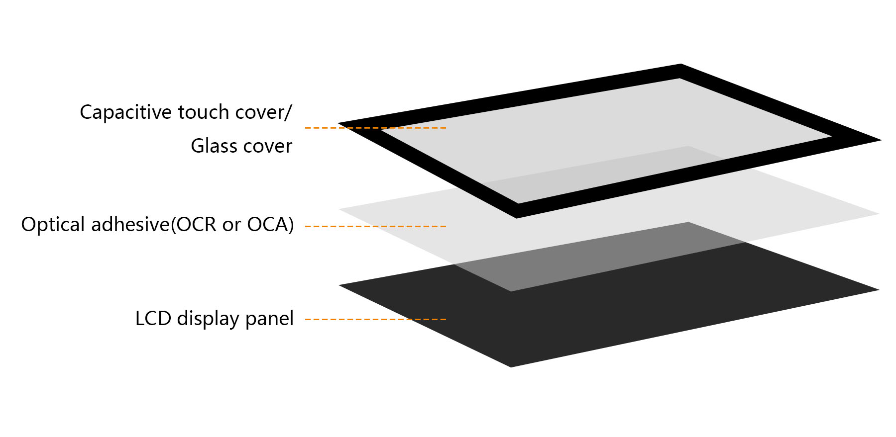
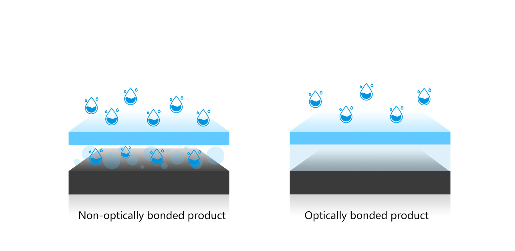
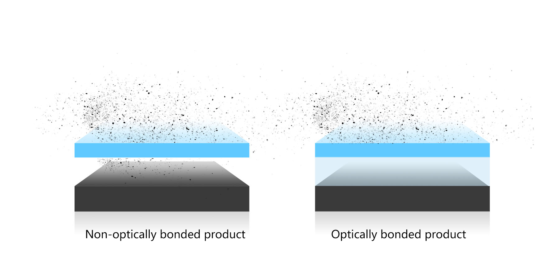
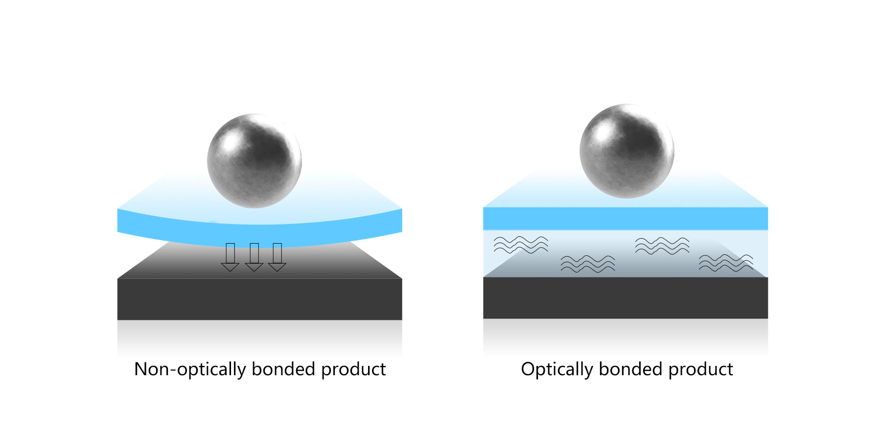
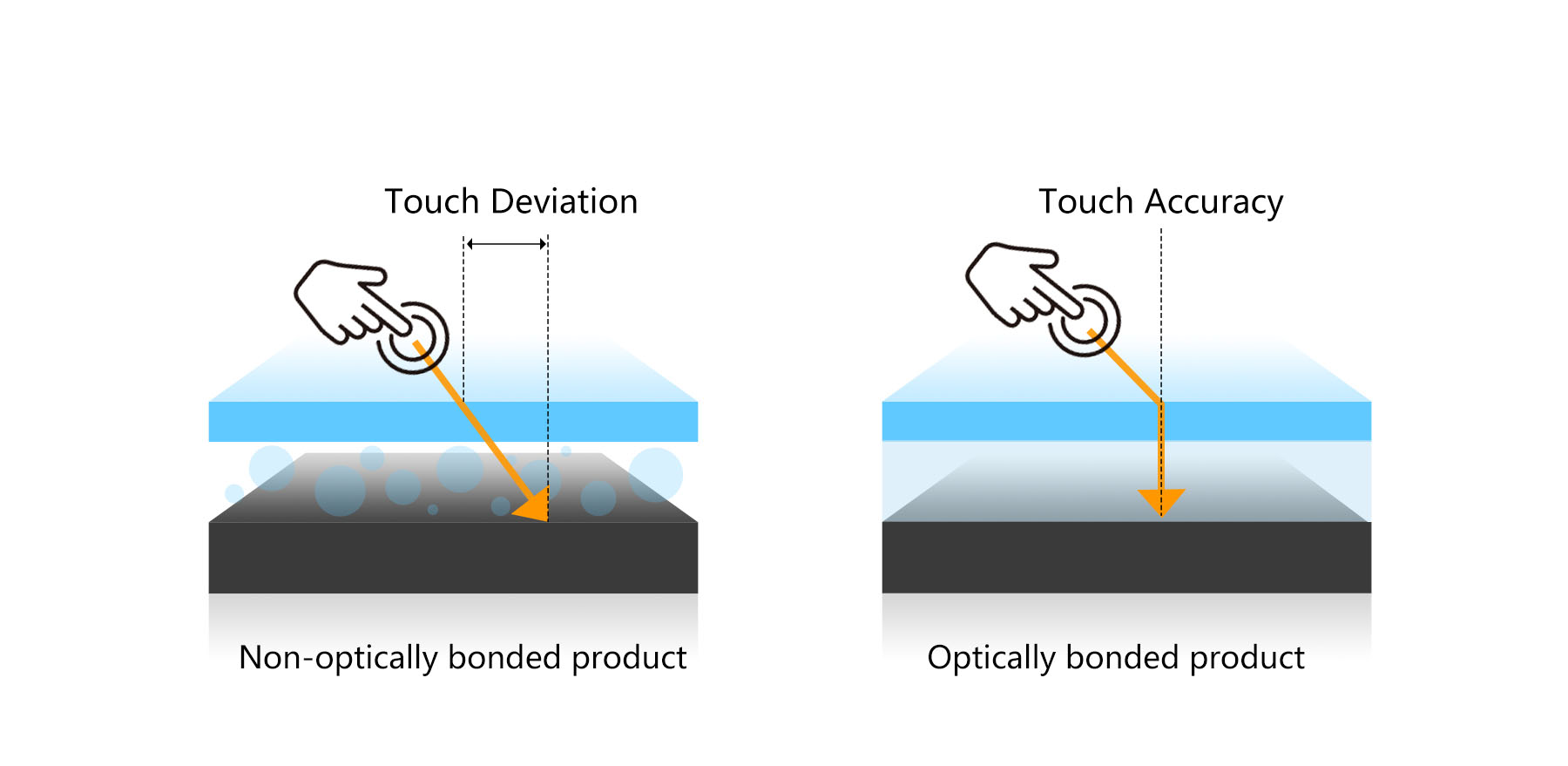
Optical bonding is a process where a transparent adhesive, such as OCR (Optical Clear Resin) or OCA (Optical Clear Adhesive), is used to directly bond the LCD panel with the protective glass or touch cover. The aim is to eliminate the air gap between the two layers, reducing light reflection and enhancing the display’s visibility. Optical bonding is widely applied in outdoor LCD displays and other devices where high performance and durability are required.

outdoor LCD displays


Benefits of Optical Bonding


Optical bonding offers numerous advantages, significantly enhancing the performance and longevity of LCD digital signage and other display solutions.

1. Reduces External Light Reflection

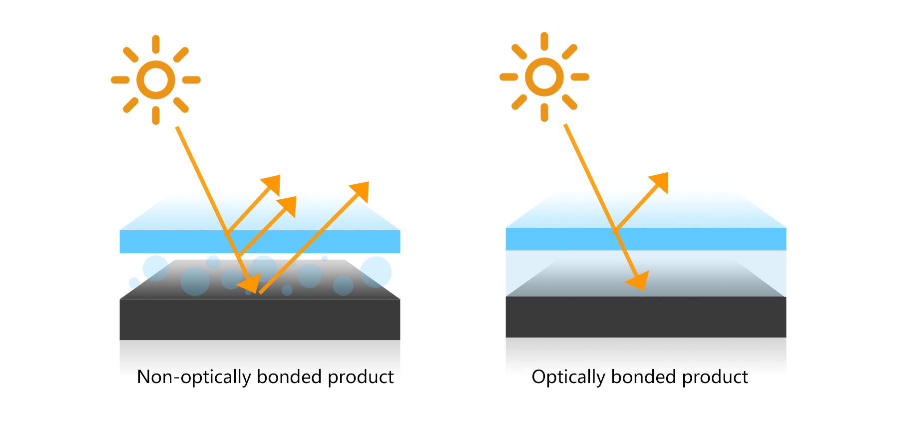
By eliminating the air gap between the LCD screen and the protective glass, optical bonding greatly reduces light reflection from external sources. This improves the contrast ratio and makes the screen easier to read, even in bright environments or direct sunlight. For outdoor LCD displays, this feature is particularly crucial for maintaining legibility.


2. Prevents Condensation

In non-optically bonded displays, the air gap can lead to moisture buildup, especially in high humidity or rapidly changing temperature environments. This condensation can blur the screen or cause long-term damage. Optical bonding creates a sealed environment, preventing moisture from entering and thus stopping condensation from forming on the LCD display panel.


3. Prevents Foreign Object Infiltration

Optical bonding also helps prevent the intrusion of dust, particles, or other foreign objects into the gap between the LCD panel and the glass cover. This keeps the display clear and free from interference, prolonging the device's lifespan. In high-brightness LCD screens, any dust particles between the layers could significantly impact the clarity of the display, which optical bonding eliminates.


4. Enhances Impact Resistance

By tightly bonding the LCD display and the glass or capacitive touch cover, the screen becomes more resistant to impact and damage. This increased durability is especially important for outdoor digital signage, where the screens are subject to more frequent physical stress.


5. Improved Touchscreen Responsiveness

In capacitive touch displays, optical bonding not only improves the display’s visual clarity but also enhances its touch sensitivity. The elimination of the air gap allows touch signals to be transmitted more quickly and accurately, providing a more responsive and seamless user experience.

Conclusion


Optical bonding plays a pivotal role in improving the performance, durability, and usability of LCD displays. By reducing external light reflection, preventing condensation, keeping foreign objects out, enhancing impact resistance, and improving touchscreen responsiveness, this technology is essential for various applications, including outdoor digital signage and LCD digital signage. As the demand for high-performance LCD solutions continues to grow, optical bonding will remain a critical factor in delivering superior display technology.

  • What is SMD Packaging Technology?
  • The Core of SMD Packaging Technology
  • Advantages of SMD Packaging Technology
  • Applications of SMD Packaging Technology


In the LED display industry, performance and image quality improvements often hinge on small but crucial technological advancements. Among them, SMD packaging technology (Surface Mount Device) is undoubtedly a driving force in the evolution of LED displays. But what exactly is SMD packaging, and how does it impact LED displays? Let’s explore.


SMD LED displays


  • What is SMD Packaging Technology?

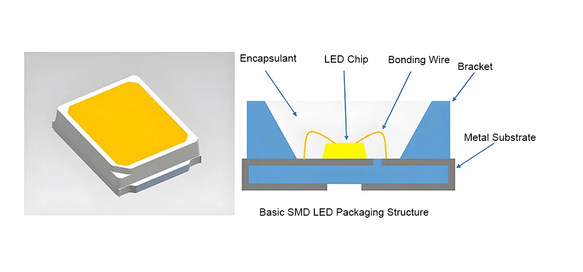
SMD packaging, short for Surface Mounted Device, involves encapsulating LED chips, supports, and bonding wires into compact, lead-free LED beads, which are then surface-mounted onto printed circuit boards (PCBs) using automated machines. Compared to traditional DIP (Dual In-Line Package) technology, SMD offers higher integration, smaller size, and lighter weight, driving miniaturization and efficient production of LED displays.

SMD LED displays

  • The Core of SMD Packaging Technology

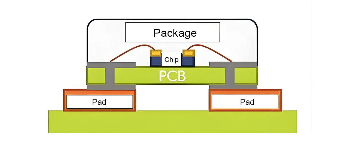
At its core, SMD packaging mounts the LED chip directly onto the surface of the circuit board rather than inserting it through traditional holes. This surface-mount approach enables the miniaturization of components, improves production efficiency, and facilitates automation.

SMD LED displays

  • Advantages of SMD Packaging Technology


High Integration and Miniaturization

SMD technology allows LED components to be compact and lightweight, ideal for high-density integration. This results in smaller pixel pitch and higher resolution, enhancing image sharpness and clarity.

Efficient Production

Automated pick-and-place machines significantly boost production efficiency. Compared to traditional manual soldering, SMD technology speeds up the mounting of numerous LED components, reducing labor costs and shortening production time.

Excellent Heat Dissipation

SMD-packaged LED components are in direct contact with the PCB, facilitating heat dissipation. Effective thermal management extends the lifespan of LEDs and enhances the stability and reliability of the display.

Easy Maintenance and Replacement

Since SMD components are surface-mounted on the PCB, they are easier to repair and replace, lowering maintenance costs and downtime.

Cost-Effective

Automated production reduces manufacturing costs, making the products more affordable.


  • Applications of SMD Packaging Technology


LED display models using SMD packaging technology are widely applied in various scenarios, including small-pitch LED displays (P1.2, P1.5), indoor displays (P2, P2.5), outdoor displays (P4-P10), as well as transparent and flexible screens. SMD technology provides these models with high resolution, wide viewing angles, strong weather resistance, and energy efficiency, making them ideal for advertising, conferences, stages, and sports venues.


SMD LED displays


SMD packaging technology is one of the key driving forces behind the advancement of the LED display industry. Its high integration, automated production benefits, and superior heat dissipation have enhanced the overall performance of LED displays, providing higher resolution, wider viewing angles, and strong weather resistance, suitable for various indoor and outdoor applications. As technological innovations continue, SMD packaging will remain a vital player in the evolution of LED display technology.

Dear beautiful people,


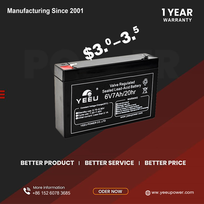
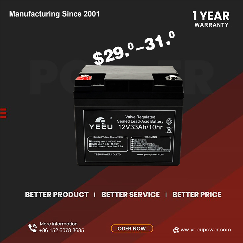
We're excited to announce our 2024 Year-End Battery Inventory Clearance Sale! This is your chance to grab incredible deals on high-quality sealed lead- acid batteries.


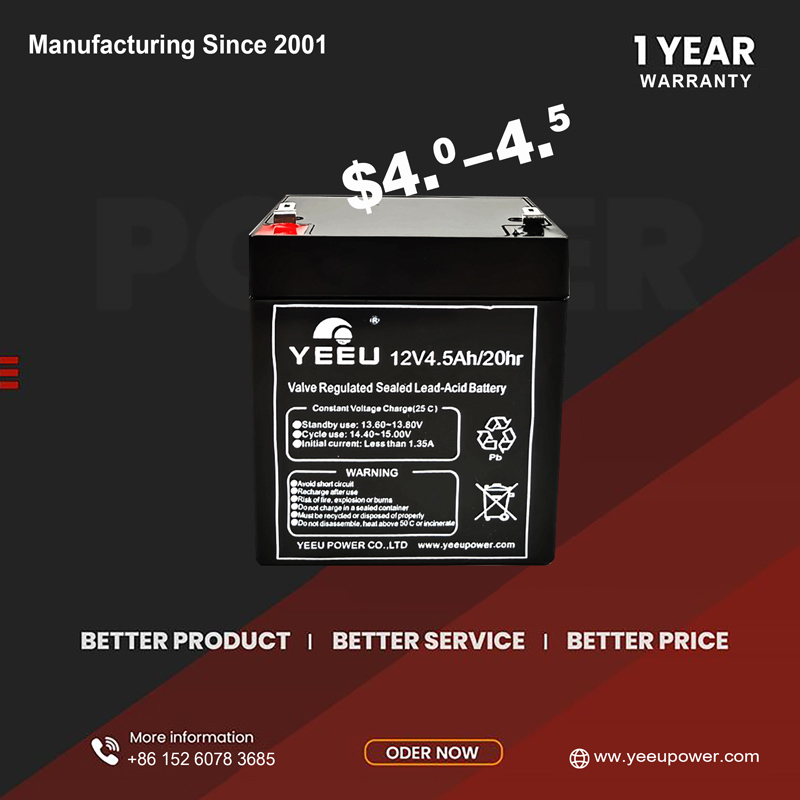
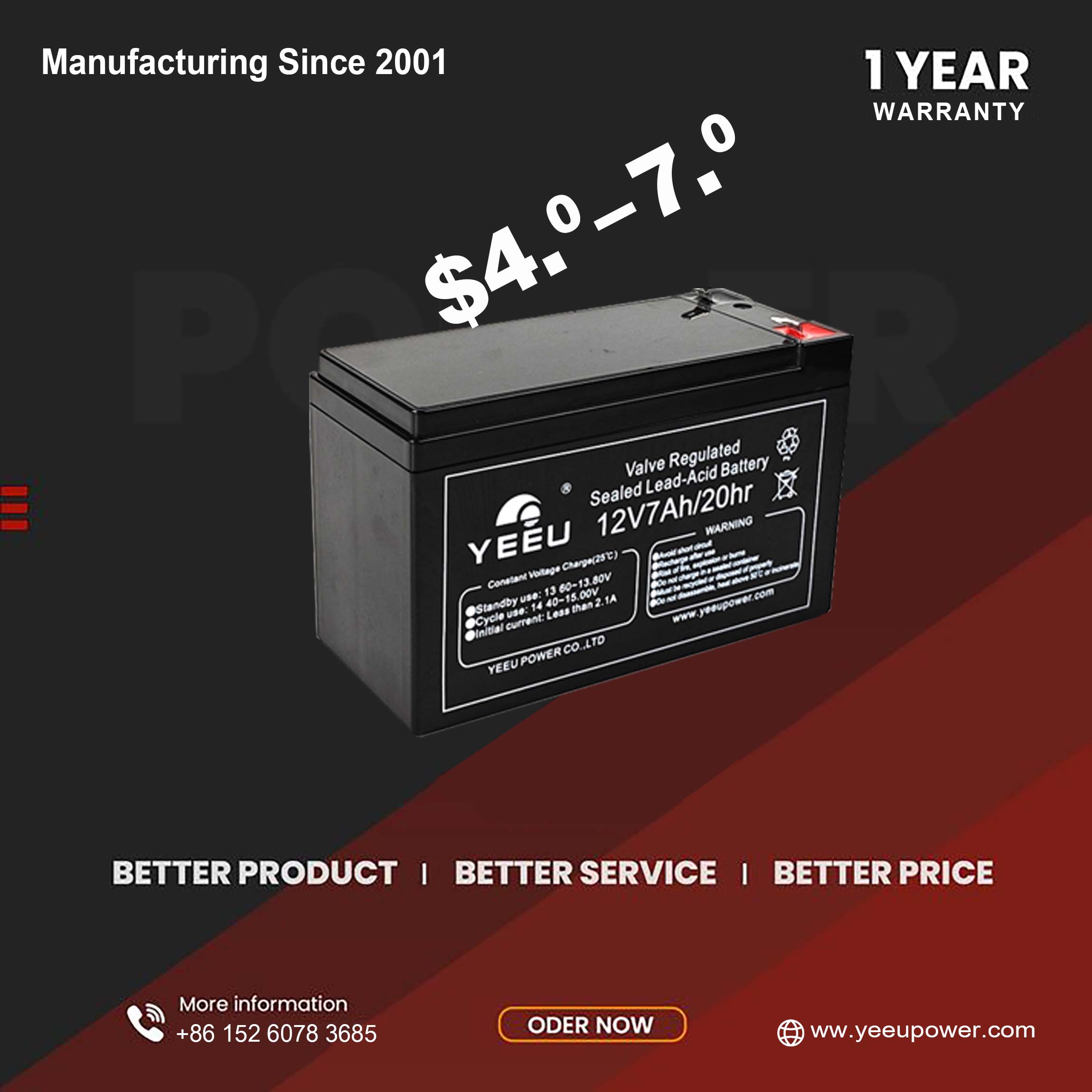
From 21st, Nov, 2024 to 31st, Dec, 2024, we'll be offering massive discounts on some of our inventory batteries, including the popular 12V4.5Ah battery and 12V7Ah battery.


You can trust that you're getting batteries that will deliver optimal performance and meet your expectations. Battery comes with 1 year warranty as always.


Don't miss out on this fantastic opportunity to save costs!

  • 6V7Ah Battery Replacement
  • 12V4.5Ah Battery VRLA
  • 12V 7.0Ah Battery
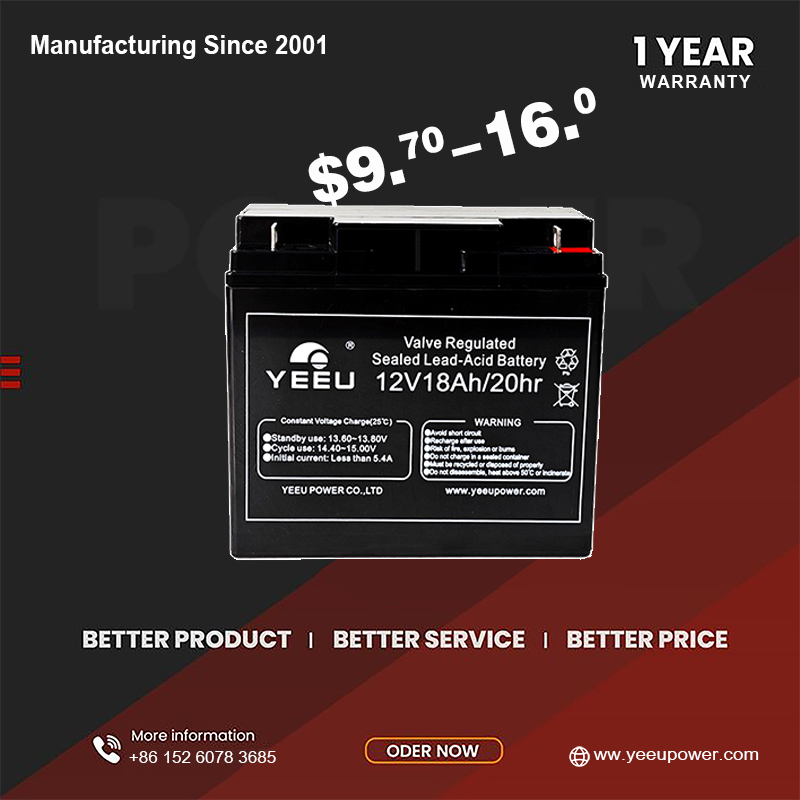
  • 12V18Ah UPS Battery
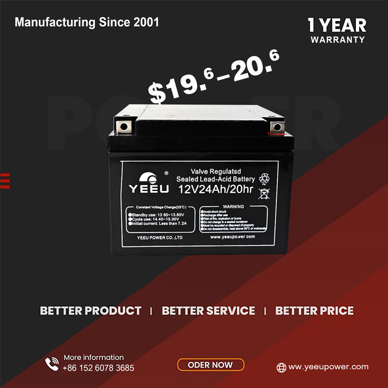
  • 12V24Ah UPS Battery
  • 12V33Ah UPS Battery


YEEU POWER CO., LTD

      21st, Nov, 2024

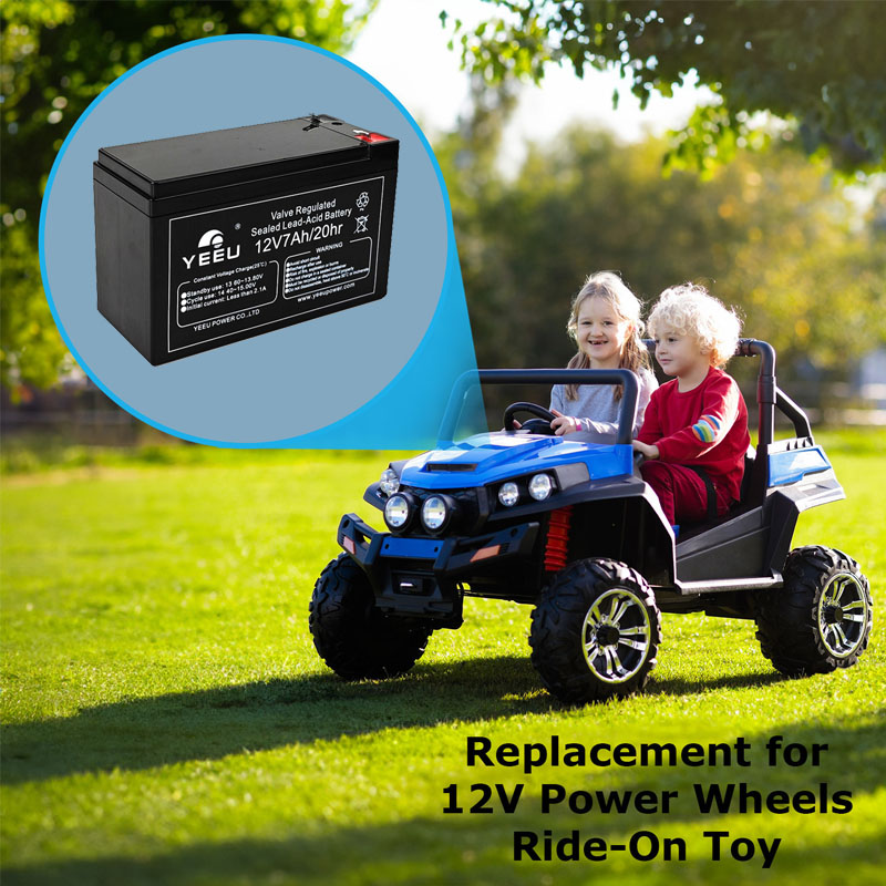
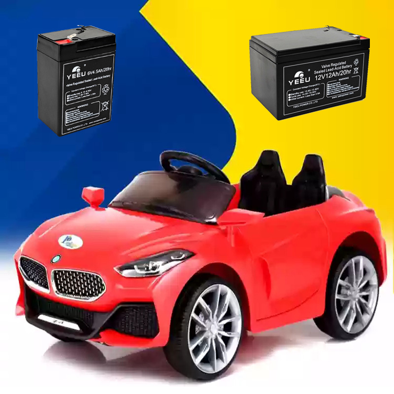
Lead-acid batteries are commonly used in kids' toy cars due to their affordability, reliability, and safety. When choosing a lead-acid battery for a kids' toy car, there are a few factors to consider:

  • Battery For Ride On Toy
     
  • 12V5Ah For Kids Toy Car
     
  • Replacement Battery For Kids Ride On Car


Battery Size

Ensure that the battery size and dimensions fit the toy car and its designated battery compartment. Check the product specifications or consult the toy car manufacturer for the compatible battery size.


Battery Capacity

The battery capacity determines how long the toy car can run before needing to be recharged. Consider the desired runtime and choose a toy car battery with an adequate capacity (measured in ampere-hours, Ah). A higher Ah rating generally indicates a longer runtime.


Voltage

Check the voltage requirement of the toy car. Most kids' toy cars operate on 6V batteries or 12V batteries, so make sure to choose a battery with the corresponding voltage. Using the wrong voltage can damage the car's electronics.


Safety Features

Look for batteries with built-in safety features such as overcharging protection, short-circuit protection, and thermal protection. These features help prevent accidents and ensure the longevity of the battery.


Brand and Quality

Opt for batteries from reputable brands known for producing high-quality products. Research customer reviews and ratings to gauge the reliability and performance of different battery brands.


Maintenance

Consider whether you prefer a maintenance-free battery or one that requires periodic maintenance, such as checking water levels and adding distilled water. Maintenance-free batteries, such as sealed lead-acid (SLA) or valve-regulated lead-acid (VRLA) batteries, are generally more convenient for kids' toy cars.


Budget

Set a budget for the battery purchase, considering factors such as capacity, brand, and warranty. Compare prices from different suppliers to find the best balance between quality and affordability.


It's also worth noting that lead-acid batteries should be charged using a compatible charger designed for them to avoid damage or safety risks. Always follow the sla battery manufacturer's instructions and guidelines for charging, maintenance, and usage of the battery.

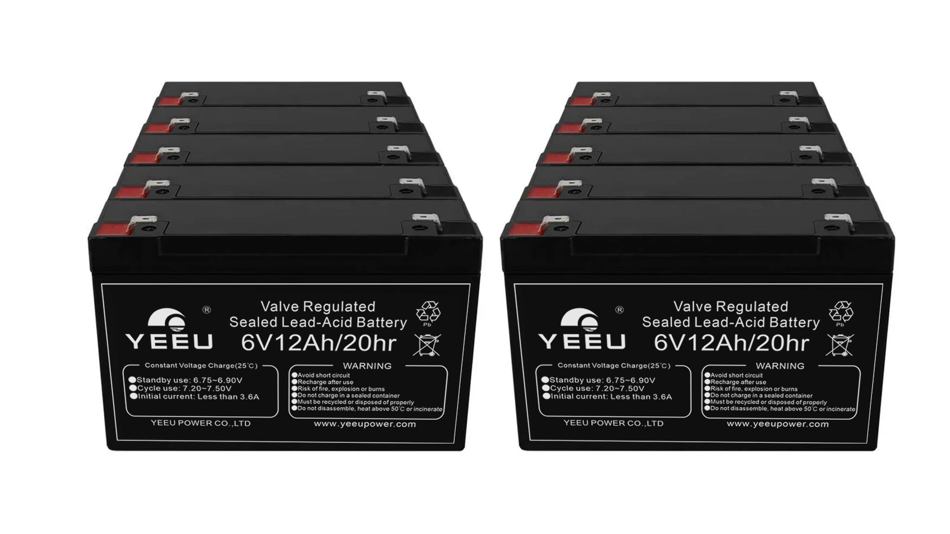
6V12Ah For Kids Toy Car

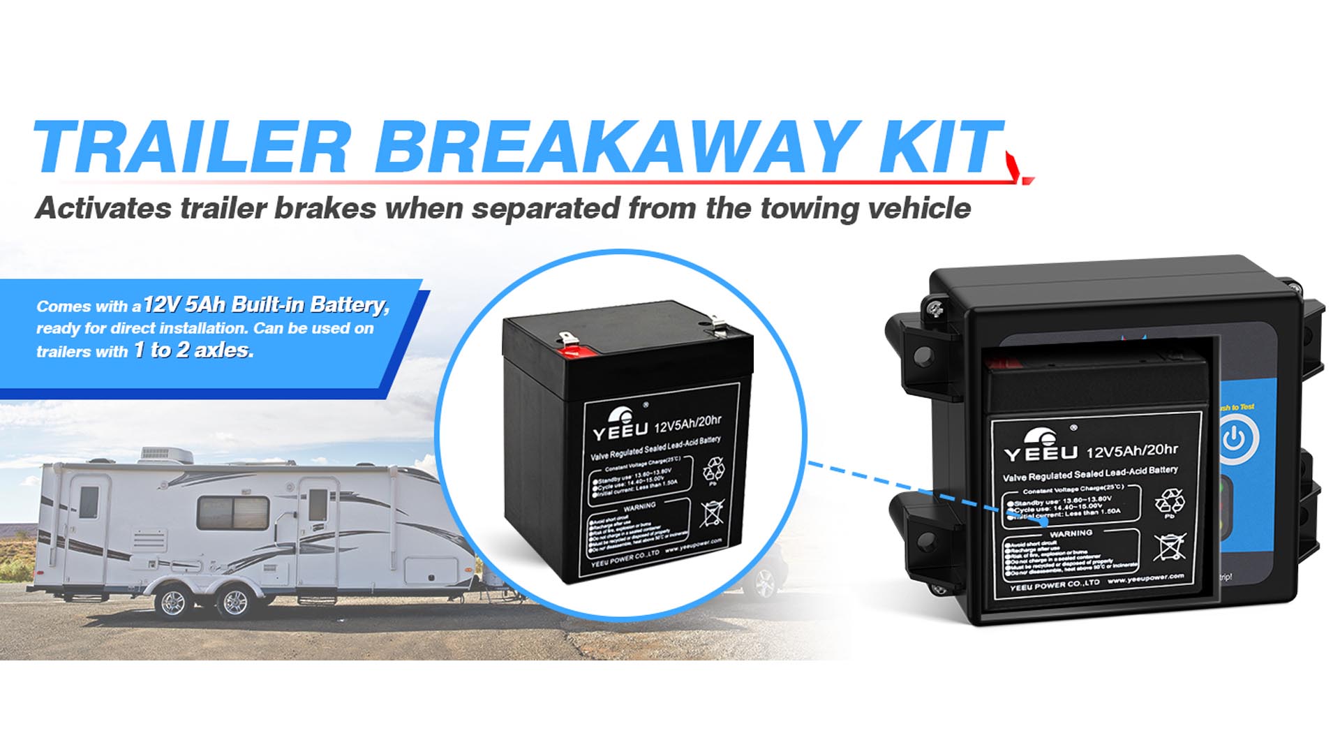
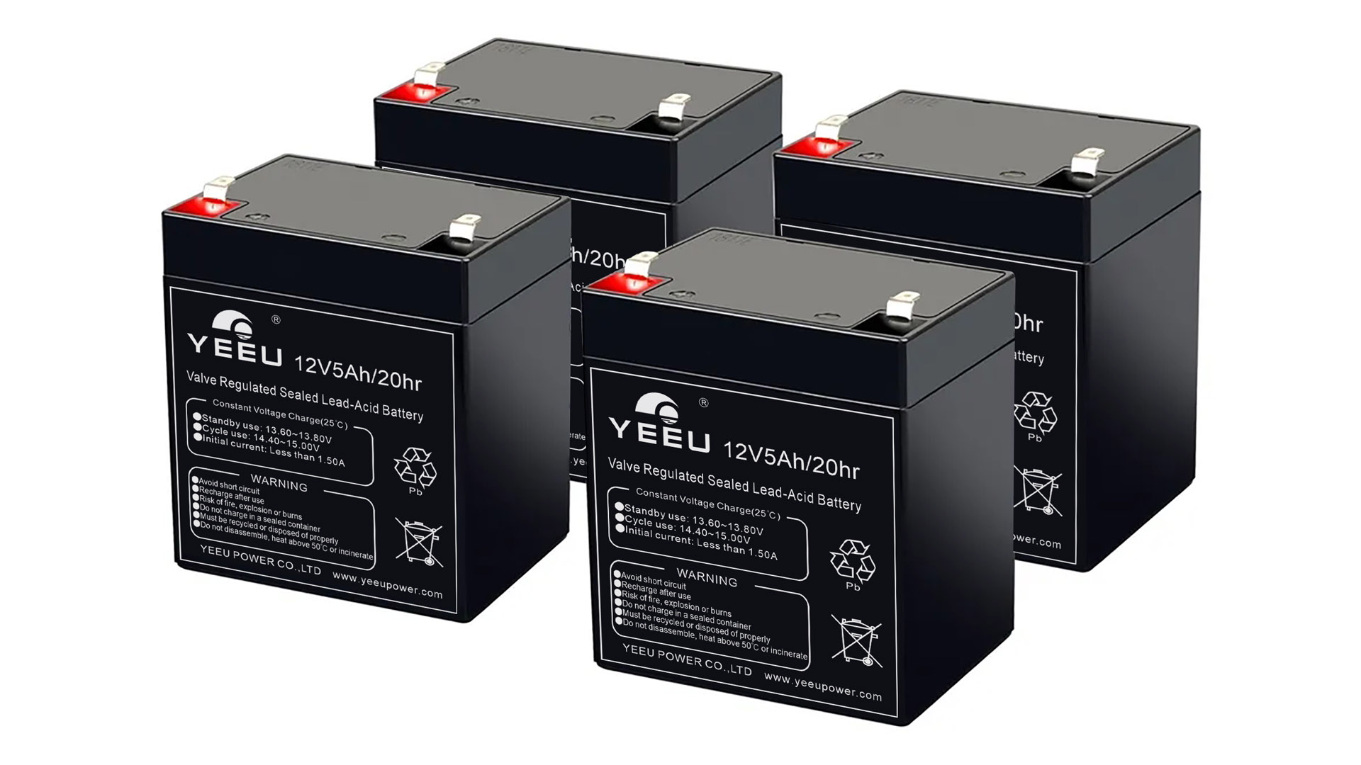
12V Battery For Breakaway System

A 12V5Ah battery is commonly used in breakaway systems for trailers and caravan setups. A breakaway system is a safety feature that activates the trailer brakes in the event of separation or detachment from the towing vehicle. The battery is a crucial component of the breakaway system, and here's why it is important:


Emergency Braking

When a trailer becomes detached from the towing vehicle, the breakaway system kicks in to engage the trailer brakes and bring it to a controlled stop. The battery provides the necessary power to activate the breakaway system and ensure the brakes engage effectively.


Power Supply

The 12V5Ah battery provides the required voltage and current to operate the breakaway system. It delivers a sufficient amount of power to activate the brakes and maintain control of the detached trailer.


Reliability

The 12V lead acid battery is known for its reliability and ability to deliver consistent power. It is capable of providing the necessary power over an extended period, ensuring that the breakaway system remains operational when needed.


Maintenance and Replacement

It is important to regularly maintain and monitor the 12V5Ah battery to ensure its optimal performance. This includes checking the charge level, ensuring proper connections, and replacing the battery as needed to ensure reliable operation of the breakaway system.


Safety Compliance

Many jurisdictions have regulations and standards for breakaway systems in trailers and caravans. These regulations often specify the type and capacity of the battery required, and using a 12V5Ah battery ensures compliance with such requirements, ensuring the safety of the towing vehicle, the trailer, and other road users.


Overall, the 12V5Ah battery is an important component of a breakaway system. It provides the power necessary to activate the brakes and ensure the safety of the towing vehicle and the detached trailer. Regular maintenance and replacement are necessary to ensure the battery's reliability and proper functioning of the break system.

12V5Ah Breakaway Trailer Battery

Temperature

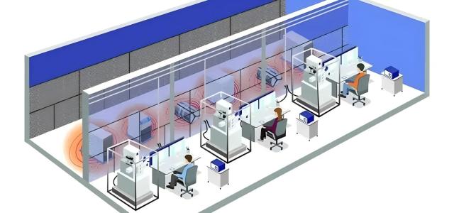
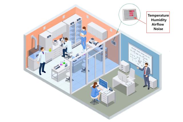
The temperature requirements for Electron Microscopes are not particularly high. Typically, temperatures around 26 degrees Celsius in summer and 20 degrees Celsius in winter are acceptable for comfort and energy efficiency. However, the temperature change rate is important, with common requirements being ≤0.5°C/3 minutes or ≤0.5°C/5 minutes.


Good-quality central air conditioning systems can usually meet these requirements. For example, a well-known brand of split air conditioner has a four-minute cycle with temperature fluctuations of around 1 degree Celsius. Using precision air conditioning systems usually doesn't offer significant benefits in terms of price, maintenance costs, and applicability.


In practice, High-precision Electron Microscopes tend to be bulky and have larger heat capacities. As long as the temperature variation inside the room is not significant, minor fluctuations within a short period are unlikely to have a noticeable impact.


It's important to avoid excessively low temperatures in the electron microscope room to prevent condensation and dripping water on cooling water pipes, liquid nitrogen pipes, and Dewar flasks. For example, there was a case where an improperly placed old-fashioned spectroscopic circuit board under a liquid nitrogen Dewar flask got damaged due to condensation dripping.


Regarding auxiliary equipment rooms, such as those housing circulation cooling water tanks, air compressors, uninterrupted power supply (UPS) units, and vacuum pumps, it's necessary to calculate the required capacity of the air conditioning system based on the heat dissipation provided in the equipment specifications.


If the temperature in the auxiliary equipment room is too high, it can reduce the cooling efficiency of the circulation cooling water tank and increase the thermal drift of lenses.


Therefore, it is recommended to keep the temperature in the auxiliary equipment room below 35 degrees Celsius throughout the year.


Humidity

Frozen samples have high humidity requirements, and some users prefer a relative humidity below 25%. However, extremely low humidity can lead to electrostatic discharge. To address this, the freeze-fracture preparation machine can be moved closer to the Electron Microscope to minimize the exposure time of frozen samples, thereby reducing the humidity requirements.


Usually, relative humidity of below 65% is sufficient for the electron microscope room, which is a relatively low requirement that most air conditioning systems can easily meet (assuming the room door is kept closed and the time for personnel entry and exit is minimized).


If it is a newly constructed building within a year, it may take some time to eliminate the building's moisture. In such cases, a dehumidifier can be added to regulate the humidity.


Airflow

Another consideration is the airflow from the air conditioning system. In most cases, as long as the air conditioning outlets (whether mounted or cabinet-type) are not directly facing the microscope column during the layout planning of the electron microscope room, the issue of airflow is generally not a major concern. For high-demand Electron Microscopes, using cloth bags for air supply can be considered.


As indicated by the formula airflow = air velocity × air outlet area, increasing the outlet area can reduce the air velocity while maintaining the same airflow.


A successful case from a university involves an approximately 50 square meter Electron Microscope room with a nearly square floor plan. Two air supply outlets (1m x 1m cross-section) were placed diagonally on the roof, and two return air outlets (0.8m x 0.8m cross-section) were placed on opposite diagonal corners. This arrangement allowed the airflows to flow along the walls, effectively achieving the air supply task, and creating a "quiet zone" near the microscope column (which is located near the center of the room). Multiple tests showed that the air velocity reached 0.00 m/s.


Noise

Noise is another issue to consider, as even the volume of a phone call can cause horizontal interference stripes (similar to jagged lines caused by magnetic interference) in images with magnifications over 100,000 times.


If it is not possible to move the noise source away, the walls and ceiling can be covered with flame-retardant foam materials for sound absorption. Micro-perforated panels (made of iron or aluminum composite panels, for example) should be used for the walls. Foam materials with a thickness of 40-80mm generally provide noticeable sound absorption effects.


In general, as long as the door is closed and no one speaks, the impact of noise interference can be negligible.

Conclusion

This series of electron microscope installation environment pictures, texts, and recommendations are based on practical experience gained from over a decade of site surveys and renovations. It holds a high reference value.


The site conditions are of significant importance to the performance of electron microscopes.


Therefore, it is highly recommended to let professionals handle their respective areas of expertise. Both users and manufacturers should engage professional companies and personnel for site surveys and renovations. In addition, a rigorous supervision mechanism and clear accountability system should be established to prevent the participation of unscrupulous practitioners and the loss of equipment efficiency.


Furthermore, the studio strongly urges electron microscope users and relevant personnel from manufacturers to actively participate and enhance their understanding of electron microscope installation environments. This will ensure that valuable national and corporate funds are utilized to their fullest.

Recently, the research teams led by Professor Aiwen Lei from Wuhan University and Professor Lin He from Lanzhou Institute of Chemical Physics, Chinese Academy of Sciences, made a significant breakthrough in asymmetric urea synthesis. Their research results, titled "Synchronous recognition of amines in oxidative carbonylation toward unsymmetrical ureas" were published in the prestigious international journal "Science" on November 15th.


Published in "Science" with the Support of CIQTEK EPR


Unsymmetrical ureas are important compounds widely used in medicine, agriculture, and materials science. The synthesis of unsymmetrical ureas through amine reactions is the most effective method. However, achieving high selectivity in synthesizing unsymmetrical ureas is challenging due to the competitive reactivity of the two amines. So far, no metal-catalyzed method can efficiently and selectively recognize and install multiple amines at the same site.


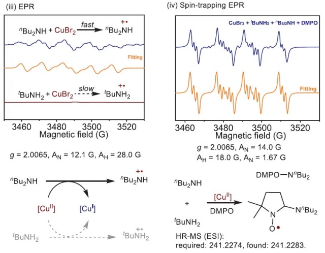
In their research, the teams deeply analyzed the electron transfer process between copper salts and amines and successfully detected the in situ-generated ammonium radical cation and its captured radical species with DMPO during the reaction. This provided crucial evidence for revealing the copper ion-mediated free radical activation mechanism of secondary amines. Combining the selective nucleophilic activation of primary amines by cobalt catalysts, the teams designed a "synchronous recognition strategy" that achieved efficient carbonylation reactions of a 1:1 molar ratio of two amines, producing highly selective unsymmetrical urea products.


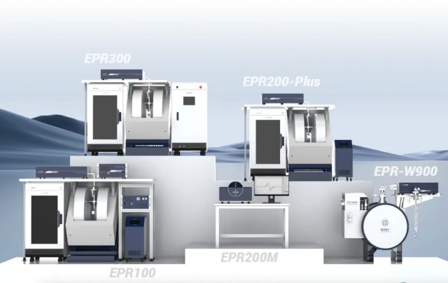
This achievement provides new avenues for the industrial production of unsymmetrical urea compounds and is expected to have broad applications in fields such as medicine and agriculture. It also demonstrates the precise characterization capabilities of the EPR spectrometer developed by CIQTEK, providing strong support for researchers to deepen their understanding of reaction mechanisms and develop innovative synthesis strategies.


The research paper was published in "Science" and can be accessed at the following link:

https://www.science.org/doi/10.1126/science.adl0149


A "Timely Rain" that Achieves Customer Satisfaction, Scripting a Success Story


Behind this achievement is a story of collaboration between CIQTEK and the research team. In October 2021, an imported EPR spectrometer at the College of Chemistry and Molecular Sciences, Wuhan University, encountered a sudden malfunction.


After contacting the manufacturer, they learned that the repair would take a long time. This posed a challenge for the experimental work of the faculty and students.


In December of the same year, at the invitation of the faculty, engineers from CIQTEK overcame the challenges posed by the pandemic and arrived on-site to troubleshoot the issue. They quickly identified a problem with the magnet power supply and immediately provided a solution.


On the same day, they completed the hardware repair, performance calibration, and standard sample testing, restoring the equipment to normal operation.


The university expressed its gratitude to CIQTEK, stating, "During the instrument failure, our college was unable to use the equipment for experimental work for two months.


The support provided by CIQTEK was like a 'timely rain,' allowing us to continue with multiple research projects. In this equipment repair, we witnessed the solid and reliable technical expertise of CIQTEK's EPR team and experienced the high sense of responsibility of high-end scientific instrument manufacturers. The team's quick response, strong capabilities, and high efficiency exemplify the model of scientific instrument manufacturers."


In 2023, the Center for Optoelectronic Nanocatalysis and Industrial Applications at the Wuhan University Institute of Advanced Studies introduced the EPR spectrometer, which played a significant role in the team's research. As CIQTEK continues to make breakthroughs in EPR spectrometers, the company is also increasing its efforts to cultivate professional talent.


From Technology to Talent, Together Towards an Innovative Future


The achievement is closely related to the in-depth research of the team led by Professor Lei Aiwen at Wuhan University in the field of Electron Paramagnetic Resonance (EPR) technology. Over the past four months, Lei Aiwen's team has continuously published high-level research papers in "Science" (2 papers), "Nature" and "Nature Chemistry".


CIQTEK, in collaboration with the University of Science and Technology of China and the Instrument Application Demonstration Center of the Chinese Academy of Sciences, has established three major course systems:


Advanced EPR Workshop 


Spectroscopy Campus Tour


EPR Application Sharing and Exchange Conference.


Through these courses, which gradually progress in complexity and combine theory with practice, multidisciplinary interaction in Magnetic Resonance Spectroscopy is continuously promoted.


In October of this year, CIQTEK officially released the world's first AI-EPR Spectrometer, achieving a breakthrough in the field. In the future, with the continuous advancement of EPR technology and ongoing product innovation, this powerful scientific research tool will undoubtedly help more research teams overcome technical barriers and promote continuous original breakthroughs in chemistry, materials, biology, and other fields.

 EPR Spectroscopy


What Are the Features and Benefits of Using RT/duroid 6010.2LM PCB?


Welcome to a comprehensive overview of RT/duroid 6010.2LM, a cutting-edge ceramic-PTFE composite laminate designed for electronic and microwave circuit applications. With its high dielectric constant and exceptional performance characteristics,RT/duroid 6010.2LM 50mil PCB empowers engineers to optimize circuit size reduction, achieve low loss at X-band frequencies and below, and ensure repeatable circuit performance. In this blog, we delve deep into the features, benefits, construction details, statistics, and typical applications of this remarkable PCB material.


Introduction of RT/duroid 6010.2LM

RT/duroid 6010.2LM laminates are engineered ceramic-PTFE composites specifically developed to meet the demands of electronic and microwave circuit applications. These high frequency laminates boast a high dielectric constant (Dk), enabling designers to reduce circuit size while maintaining excellent performance. The exceptional Dk of 10.2 +/- 0.25 at 10GHz, combined with low loss characteristics (dissipation factor of .0023 at 10GHz), makes RT/duroid 6010.2LM an ideal choice for applications where reliable signal transmission is critical.


RT duroid 6010.2LM PCB


Features

Rogers 6010.2LM offers a comprehensive range of features that make it a standout choice for electronic and microwave circuit designers:


1)Dk of 10.2 +/- 0.25 at 10GHz:

Enables circuit size reduction without compromising performance.

Low dissipation factor: With a dissipation factor of .0023 at 10GHz, this material ensures minimal signal loss.


2)High decomposition temperature:

RT/duroid 6010.2LM boasts a TGA decomposition temperature (Td) of 500°C, ensuring excellent stability under high-temperature conditions.


3)Low moisture absorption:

With a moisture absorption rate of just 0.01%, this material minimizes the effects of moisture on electrical loss.


4)Coefficient of thermal expansion:

The material exhibits a low Z-axis expansion, ensuring reliable plated through holes in multilayer boards.


5)Excellent thermal conductivity:

With a thermal conductivity of 0.86W/mk, heat is efficiently dissipated, enabling excellent thermal management.


6)Flammability rating:

RT/duroid 6010.2LM carries a V-0 UL94 flammability rating, indicating its self-extinguishing properties in case of fire.


Benefits

The advantages offered by RT/duroid 6010.2LM Rogers PCB material make it an exceptional choice for electronic and microwave circuit applications. Some key benefits include:


1)Circuit size reduction:

The high dielectric constant of this material allows designers to reduce the size of their circuits without sacrificing performance.


2)Low loss at X-band or below:

With its low dissipation factor, RT/duroid 6010.2LM excels in applications operating at X-band frequencies and below, ensuring reliable and efficient signal transmission.


3)Reliable plated through holes:

The low Z-axis expansion of this material ensures the integrity and longevity of plated through holes in multilayer boards, enhancing overall reliability.


4)Minimal moisture absorption:

The low moisture absorption rate of RT/duroid 6010.2LM mitigates the negative effects of moisture, reducing electrical loss and enhancing the overall performance of the circuit.


Repeatable performance:

Through tightεr and thickness control, this material delivers consistent circuit performance, ensuring reliable operation in a variety of conditions.


PCB Construction and Stackup

The RT/duroid 6010.2LM PCB is a double layer circuit board with the following specifications:

Copper layer 1: 35μm

Rogers RT/duroid 6010.2LM Core: 1.27 mm (50mil)

Copper layer 2: 35μm


The finished board thickness is 1.39mm, with a finished copper weight of 1oz (1.4 mils) on the outer layers. The via plating thickness is 20μm, and the surface finish is immersion gold. The PCB also features a green top solder mask, white top silkscreen, and no bottom solder mask or bottom silkscreen.


PCB Construction Details

The Rogers 6010.2LM PCB boasts the following construction details:


Board dimensions: The board measures 78mm x 98mm with a tolerance of +/- 0.15mm.

Minimum Trace/Space: The board supports a minimum trace/space width of 5/6 mils, enabling precise routing and compact circuit designs.

Minimum Hole Size: Holes as small as 0.4mm can be accommodated.

No blind vias: The PCB does not support blind vias.

100% Electrical Test: Each board undergoes a comprehensive electrical test to ensure its functionality prior to shipment.


PCB Statistics

The RT/duroid 6010.2LM 50mil Rogers substrate PCB presents the following statistical specifications:


Components: The PCB supports up to 12 components.

Total Pads: A total of 36 pads are available for component and interconnection purposes.

Thru Hole Pads: The PCB provides 22 thru-hole pads for versatile connectivity options.

Top SMT Pads: There are 14 top surface mount technology (SMT) pads available for compact and efficient component placement.

Bottom SMT Pads: The PCB does not support bottom surface mount technology (SMT) pads.

Vias: The PCB supports 25 vias for interconnecting signal layers and achieving efficient routing.

Nets: There are 2 nets on the PCB, enabling various signal paths.


Type of Artwork Supplied and Quality Standard

The RT/duroid 6010.2LM PCB accepts Gerber RS-274-X format for artwork, ensuring compatibility with industry-standard electronic design automation (EDA) tools. It adheres to IPC-Class-2 quality standards, guaranteeing a high level of manufacturing precision and reliability.


Availability

The RT/duroid 6010.2LM PCB is available worldwide, empowering engineers and designers globally to leverage its exceptional capabilities for their electronic and microwave circuit applications.


Typical Applications

RT/duroid 6010.2LM 50mil Rogers material PCBs find extensive usage in a wide range of applications, including:


1)Patch Antennas:

These PCBs enable the efficient construction of high-performance patch antennas used in wireless communication systems.


2)Satellite Communications Systems:

RT/duroid 6010.2LM PCBs play a crucial role in satellite communications systems, ensuring reliable signal transmission in space.


3)Power Amplifiers:

The exceptional performance characteristics of these PCBs make them ideal for power amplifier designs, enabling enhanced power handling and efficient signal transmission.


4)Aircraft Collision Avoidance Systems:

RT/duroid 6010.2LM PCBs contribute to the safety and reliability of aircraft collision avoidance systems by providing a dependable signal transmission medium.


Ground Radar Warning Systems: These PCBs help enable the swift detection and warning of radar signals, supporting efficient ground radar warning systems.


Conclusion

RT/duroid 6010.2LM PCBs, with their high dielectric constant, low loss, and reliable performance, empower engineers to design and develop advanced electronic and microwave circuits. These Rogers PCBs provide exceptional features and benefits, ensuring circuit size reduction, low loss at X-band frequencies and below, and reliable operation. With worldwide availability, RT/duroid 6010.2LM high frequency PCBs are poised to revolutionize the field of electronic and microwave circuit applications, enabling cutting-edge innovations and ensuring consistent performance in environments.


What Is TLY-5Z PCB?


Introduction

Welcome to our comprehensive product description of the TLY-5Z PCB 10mil Taconic material. With its cutting-edge design and advanced features, the TLY-5Z PCB is set to revolutionize the world of electronic circuitry. In this blog post, we will delve into the key characteristics, benefits, construction details, and applications of this exceptional laminated PCB. Whether you are an industry professional or an electronics enthusiast, this informative guide will provide a deeper understanding of the TLY-5Z PCB's capabilities and why it is the ideal choice for your next project.


Introduction of TLY-5Z

The TLY-5Z laminates are at the forefront of technology, offering exceptional performance for a variety of applications. These laminates feature glass-filled PTFE composites with woven fiberglass reinforcement, making them ideal for low-density applications in the aerospace industry that require minimized weight. Unlike non-reinforced PTFE, the TLY-5Z laminates provide dimensional stability while also offering a low Z-axis expansion rate. This advanced composite showcases superior thermal stability, specifically in relation to Z-axis expansion-induced stress on plated through holes. With TLY-5Z, you can achieve performance levels previously unattainable with conventional low dielectric constant PTFE composites.


TLY-5Z high frequency PCB


Features

The TLY-5Z PCB boasts an impressive array of features, engineered to deliver exceptional performance and reliability. Here are the key features at a glance:


2.1 DK of 2.2 +/- 0.04 at 10 GHz/23°C:

The TLY-5Z PCB offers a stable dielectric constant, ensuring consistent signal integrity at high frequencies.


2.2 Dissipation factor of 0.0015 at 10 GHz/23°C:

This low dissipation factor minimizes energy loss and improves overall efficiency.


2.3 TcDK of -72 ppm/°C ranging -55~150°C:

The TLY-5Z PCB exhibits excellent thermal stability, making it suitable for applications exposed to varying temperature conditions.


2.4 Moisture Absorption 0.03%:
With minimal moisture absorption, the TLY-5Z PCB remains stable and reliable over extended periods.


2.5 CTE in X-axis of 30 ppm/°C, Y-axis of 40 ppm/°C, and Z-axis of 130 ppm/°C:

The balanced coefficient of thermal expansion (CTE) ensures dimensional stability, reducing the risk of warping and other mechanical issues in the PCB.


2.6 UL-94 V0 Flammability Rating:

This high flame-retardancy rating ensures compliance with stringent safety standards, making the TLY-5Z PCB suitable for applications where fire safety is critical.


Benefits

The TLY-5Z 10mil Taconic substrate PCB offers several advantages that set it apart from traditional alternatives. Consider the following benefits when choosing the TLY-5Z for your next project:


3.1 Low Z Axis CTE:

The TLY-5Z's low Z-axis CTE ensures excellent dimensional stability, minimizing the risk of reliability issues such as plated through hole failures caused by thermal expansion.


3.2 Plated Through Hole Stability:

With its exceptional thermal stability and low Z-axis expansion, the TLY-5Z PCB provides reliable and consistent performance for plated through holes, ensuring excellent signal transmission across the entire board.


3.3 Low Density (1.92 g/cm³):

The TLY-5Z's low density design contributes to reduced weight and enhanced overall performance, making it an ideal choice for aerospace applications and any other weight-sensitive projects.


3.4 Attractive Price/Performance Ratio:

Despite its advanced features, the TLY-5Z PCB offers a competitive price/performance ratio, providing excellent value for your investment.


3.5 Excellent Peel Strength:

The TLY-5Z features outstanding peel strength, allowing it to withstand harsh environments and offering resistance against delamination and other mechanical stresses.


3.6 Compatible with Profile Copper Foil:

The TLY-5Z is well-suited for use with profile copper foil, enabling efficient signal transfer and enhancing overall electrical performance.


TLY-5Z 10mil Taconic PCB


Stackup: 2-layer rigid PCB

The TLY-5Z PCB is designed as a 2-Layer 10mil Circuit Board PCB, featuring the following stackup:


Copper_layer_1: 35μm

TLY-5Z: 0.254 mm (10mil)

Copper_layer_2: 35μm


This configuration ensures optimal signal integrity and efficient power distribution, meeting the requirements of a wide range of applications.


PCB Construction Details

The TLY-5Z PCB is meticulously crafted to meet the highest quality standards. Here are the construction details of this exceptional PCB:


Board dimensions: The TLY-5Z PCB measures 90.17mm x 41.36mm, providing a compact yet versatile platform for your electronic designs.


Minimum Trace/Space: Achieve precise designs with a minimum trace/space requirement of 5/6 mils, ensuring efficient routing and reducing the risk of signal interference.


Minimum Hole Size: The TLY-5Z PCB supports a minimum hole size of 0.2mm, allowing for intricate designs and facilitating the use of smaller components.


No Blind Vias: The absence of blind vias simplifies the manufacturing and assembly process, reducing costs and ensuring consistent quality.


Finished Board Thickness: The TLY-5Z PCB boasts a finished board thickness of 0.3mm, striking a balance between durability and flexibility in a wide range of applications.


Finished Cu Weight: The outer layers of the TLY-5Z PCB have a finished copper weight of 1oz (1.4 mils), guaranteeing excellent conductivity and efficient power distribution.


Via Plating Thickness: The TLY-5Z PCB features via plating thickness of 20μm, ensuring robust connections and minimizing the risk of signal loss.


Surface Finish: The TLY-5Z PCB comes with an immersion gold surface finish, enhancing the PCB's durability, solderability, and resistance to oxidation.


Top and Bottom Silkscreen: The TLY-5Z PCB does not include top or bottom silkscreen, allowing for a clean, minimalist aesthetic.


Top and Bottom Solder Mask: The TLY-5Z PCB does not include top or bottom solder mask, giving you flexibility in customization and allowing for specific requirements.


100% Electrical Test: Each TLY-5Z PCB undergoes a comprehensive 100% electrical test prior to shipment, ensuring the highest level of quality control and guaranteeing reliable performance.


PCB Statistics

To provide further insight into the capabilities of the TLY-5Z 10mil Taconic laminates PCB, consider the following statistics:


Components: The TLY-5Z PCB supports up to 12 components, allowing for complex electronic designs.


Total Pads: With a total of 44 pads, the TLY-5Z PCB offers ample room for component placement and ensures convenient connectivity.


Thru Hole Pads: The TLY-5Z PCB includes 25 thru-hole pads, providing options for both through-hole and surface mount components.


Top SMT Pads: Deliver versatility with 19 top surface mount technology (SMT) pads, allowing for a variety of component options.


Bottom SMT Pads: The TLY-5Z PCB does not include bottom SMT pads, optimizing space and making it ideal for single-sided assembly.


Vias: Enjoy the flexibility of 31 vias, enabling efficient layer-to-layer connections and enhancing signal integrity.


Nets: The TLY-5Z PCB boasts 2 nets, ensuring reliable signal transmission across the entire board.


Artwork and Standards

The TLY-5Z 10mil Substrate PCB follows the Gerber RS-274-X artwork format and adheres to the IPC-Class-2 standard, ensuring industry-wide compatibility and reliable performance.


Availability

The TLY-5Z 10mil Taconic PCB materials is available for purchase worldwide, allowing customers from various regions to benefit from its exceptional features and performance.


Typical Applications

The TLY-5Z Taconic PCB finds application in a wide range of industries, including:


1.Aerospace Components:

The TLY-5Z PCB 10mil's low density and dimensional stability make it an excellent choice for aerospace applications that require lightweight, high-performance materials.


2.Low Weight Antennas for Aircraft:

With its low Z axis expansion and reliable plated through hole stability, the TLY-5Z PCB 10mil is ideal for designing low-weight antennas for aircraft communication systems.


3.RF Passive Components:

TLY-5Z PCB 10mil's excellent dielectric properties and low dissipation factor make it suitable for RF passive components, enabling efficient signal transmission and reduced losses.


Conclusion

The TLY-5Z PCB 10mil is a revolutionary product that combines advanced glass-filled PTFE composites with woven fiberglass reinforcement. With its superior thermal stability, low Z-axis expansion, and exceptional performance characteristics, the TLY-5Z Taconic TLX PCB is the ideal choice for aerospace components, lightweight antennas for aircraft, RF passive components, and a variety of high-performance applications. Its low density, attractive price-to-performance ratio, and compatibility with profile copper foil set it apart from traditional PCB alternatives. Choose the TLY-5Z high frequency PCB for your next project and unlock limitless possibilities in electronic circuitry.